

304
J. Seeman et al.
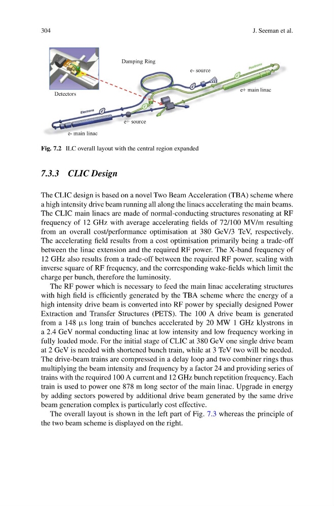
e- source
e+ main linac
e+ source
e- main linac
Detectors
Damping Ring
Fig. 7.2 ILC overall layout with the central region expanded
7.3.3 CLIC Design
The CLIC design is based on a novel Two Beam Acceleration (TBA) scheme where
a high intensity drive beam running all along the linacs accelerating the main beams.
The CLIC main linacs are made of normal-conducting structures resonating at RF
frequency of 12 GHz with average accelerating fields of 72/100 MV/m resulting
from an overall cost/performance optimisation at 380 GeV/3 TeV, respectively.
The accelerating field results from a cost optimisation primarily being a trade-off
between the linac extension and the required RF power. The X-band frequency of
12 GHz also results from a trade-off between the required RF power, scaling with
inverse square of RF frequency, and the corresponding wake-fields which limit the
charge per bunch, therefore the luminosity.
The RF power which is necessary to feed the main linac accelerating structures
with high field is efficiently generated by the TBA scheme where the energy of a
high intensity drive beam is converted into RF power by specially designed Power
Extraction and Transfer Structures (PETS). The 100 A drive beam is generated
from a 148 μs long train of bunches accelerated by 20 MW 1 GHz klystrons in
a 2.4 GeV normal conducting linac at low intensity and low frequency working in
fully loaded mode. For the initial stage of CLIC at 380 GeV one single drive beam
at 2 GeV is needed with shortened bunch train, while at 3 TeV two will be needed.
The drive-beam trains are compressed in a delay loop and two combiner rings thus
multiplying the beam intensity and frequency by a factor 24 and providing series of
trains with the required 100 A current and 12 GHz bunch repetition frequency. Each
train is used to power one 878 m long sector of the main linac. Upgrade in energy
by adding sectors powered by additional drive beam generated by the same drive
beam generation complex is particularly cost effective.
The overall layout is shown in the left part of Fig. 7.3 whereas the principle of
the two beam scheme is displayed on the right.
J. Seeman et al.
e- source
e+ main linac
e+ source
e- main linac
Detectors
Damping Ring
Fig. 7.2 ILC overall layout with the central region expanded
7.3.3 CLIC Design
The CLIC design is based on a novel Two Beam Acceleration (TBA) scheme where
a high intensity drive beam running all along the linacs accelerating the main beams.
The CLIC main linacs are made of normal-conducting structures resonating at RF
frequency of 12 GHz with average accelerating fields of 72/100 MV/m resulting
from an overall cost/performance optimisation at 380 GeV/3 TeV, respectively.
The accelerating field results from a cost optimisation primarily being a trade-off
between the linac extension and the required RF power. The X-band frequency of
12 GHz also results from a trade-off between the required RF power, scaling with
inverse square of RF frequency, and the corresponding wake-fields which limit the
charge per bunch, therefore the luminosity.
The RF power which is necessary to feed the main linac accelerating structures
with high field is efficiently generated by the TBA scheme where the energy of a
high intensity drive beam is converted into RF power by specially designed Power
Extraction and Transfer Structures (PETS). The 100 A drive beam is generated
from a 148 μs long train of bunches accelerated by 20 MW 1 GHz klystrons in
a 2.4 GeV normal conducting linac at low intensity and low frequency working in
fully loaded mode. For the initial stage of CLIC at 380 GeV one single drive beam
at 2 GeV is needed with shortened bunch train, while at 3 TeV two will be needed.
The drive-beam trains are compressed in a delay loop and two combiner rings thus
multiplying the beam intensity and frequency by a factor 24 and providing series of
trains with the required 100 A current and 12 GHz bunch repetition frequency. Each
train is used to power one 878 m long sector of the main linac. Upgrade in energy
by adding sectors powered by additional drive beam generated by the same drive
beam generation complex is particularly cost effective.
The overall layout is shown in the left part of Fig. 7.3 whereas the principle of
the two beam scheme is displayed on the right.