

7 Design and Principles of Linear Accelerators and Colliders
303
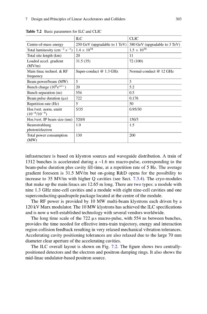
Table 7.2 Basic parameters for ILC and CLIC
ILC
CLIC
Centre-of-mass energy
250 GeV (upgradable to 1 TeV) 380 GeV (upgradable to 3 TeV)
Total luminosity (cm −2 s −1 ) 1.4 × 10 34
1.5 × 10 34
Total site length (km)
20
11
Loaded accel. gradient
(MV/m)
31.5 (35)
72 (100)
Main linac technol. & RF
frequency
Super-conduct @ 1.3 GHz
Normal-conduct @ 12 GHz
Beam power/beam (MW)
5
3
Bunch charge (10 9 e +/− )
20
5.2
Bunch separation (ns)
554
0.5
Beam pulse duration (μs)
722
0.176
Repetition rate (Hz)
5
50
Hor./vert. norm. emitt
(10 −6 /10 −9 )
5/35
0.95/30
Hor./vert. IP beam size (nm) 520/8
150/3
Beamstrahlung
photon/electron
1.9
1.5
Total power consumption
(MW)
130
200
infrastructure is based on klystron sources and waveguide distribution. A train of
1312 bunches is accelerated during a ~1.6 ms macro-pulse, corresponding to the
beam-pulse duration plus cavity fill-time, at a repetition rate of 5 Hz. The average
gradient foreseen is 31.5 MV/m but on-going R&D opens for the possibility to
increase to 35 MV/m with higher Q cavities (see Sect. 7.3.4). The cryo-modules
that make up the main linacs are 12.65 m long. There are two types: a module with
nine 1.3 GHz nine-cell cavities and a module with eight nine-cell cavities and one
superconducting quadrupole package located at the centre of the module.
The RF power is provided by 10 MW multi-beam klystrons each driven by a
120 kV Marx modulator. The 10 MW klystrons has achieved the ILC specifications
and is now a well-established technology with several vendors worldwide.
The long time scale of the 722 μs macro-pulse, with 554 ns between bunches,
provides the time needed for effective intra-train trajectory, energy and interaction
region collision feedback resulting in very relaxed mechanical vibration tolerances.
Accelerating cavity positioning tolerances are also relaxed due to the large 70 mm
diameter clear aperture of the accelerating cavities.
The ILC overall layout is shown on Fig. 7.2. The figure shows two centrallypositioned detectors and the electron and positron damping rings. It also shows the
mid-linac undulator-based positron source.
303
Table 7.2 Basic parameters for ILC and CLIC
ILC
CLIC
Centre-of-mass energy
250 GeV (upgradable to 1 TeV) 380 GeV (upgradable to 3 TeV)
Total luminosity (cm −2 s −1 ) 1.4 × 10 34
1.5 × 10 34
Total site length (km)
20
11
Loaded accel. gradient
(MV/m)
31.5 (35)
72 (100)
Main linac technol. & RF
frequency
Super-conduct @ 1.3 GHz
Normal-conduct @ 12 GHz
Beam power/beam (MW)
5
3
Bunch charge (10 9 e +/− )
20
5.2
Bunch separation (ns)
554
0.5
Beam pulse duration (μs)
722
0.176
Repetition rate (Hz)
5
50
Hor./vert. norm. emitt
(10 −6 /10 −9 )
5/35
0.95/30
Hor./vert. IP beam size (nm) 520/8
150/3
Beamstrahlung
photon/electron
1.9
1.5
Total power consumption
(MW)
130
200
infrastructure is based on klystron sources and waveguide distribution. A train of
1312 bunches is accelerated during a ~1.6 ms macro-pulse, corresponding to the
beam-pulse duration plus cavity fill-time, at a repetition rate of 5 Hz. The average
gradient foreseen is 31.5 MV/m but on-going R&D opens for the possibility to
increase to 35 MV/m with higher Q cavities (see Sect. 7.3.4). The cryo-modules
that make up the main linacs are 12.65 m long. There are two types: a module with
nine 1.3 GHz nine-cell cavities and a module with eight nine-cell cavities and one
superconducting quadrupole package located at the centre of the module.
The RF power is provided by 10 MW multi-beam klystrons each driven by a
120 kV Marx modulator. The 10 MW klystrons has achieved the ILC specifications
and is now a well-established technology with several vendors worldwide.
The long time scale of the 722 μs macro-pulse, with 554 ns between bunches,
provides the time needed for effective intra-train trajectory, energy and interaction
region collision feedback resulting in very relaxed mechanical vibration tolerances.
Accelerating cavity positioning tolerances are also relaxed due to the large 70 mm
diameter clear aperture of the accelerating cavities.
The ILC overall layout is shown on Fig. 7.2. The figure shows two centrallypositioned detectors and the electron and positron damping rings. It also shows the
mid-linac undulator-based positron source.