

232
B. J. Holzer et al.
6.4.3.1 Effect of Crossing Angle and Transverse Offset
Here we give the correction to the luminosity calculation in the case where two
bunches do not collide exactly head-on, but with a crossing angle and/or transverse
offset. In that case the luminosity is reduced and we must apply a correction factor
to compute the correct value. For simplicity we assume crossing angle and offset
in the horizontal (x) plane, but this is not a restriction. The integration (6.23) can
be carried out by rotating the coordinate systems of the two beams each by half the
crossing angle [37] and can be simplified introducing the factors:
A =
sin 2 φ
2
σ 2
x
+
cos 2 φ
2
σ 2
s
, B =
(d 2 −d 1 ) sin(φ/2)
2σ 2
x
, W = e
−
1
4σ 2
x
(d 2 −d 1 ) 2
(6.28)
S =
1
1 +
σ s
σ x
tan
φ
2
2
≈
1
1 +
σ s
σ x
φ
2
2
(6.29)
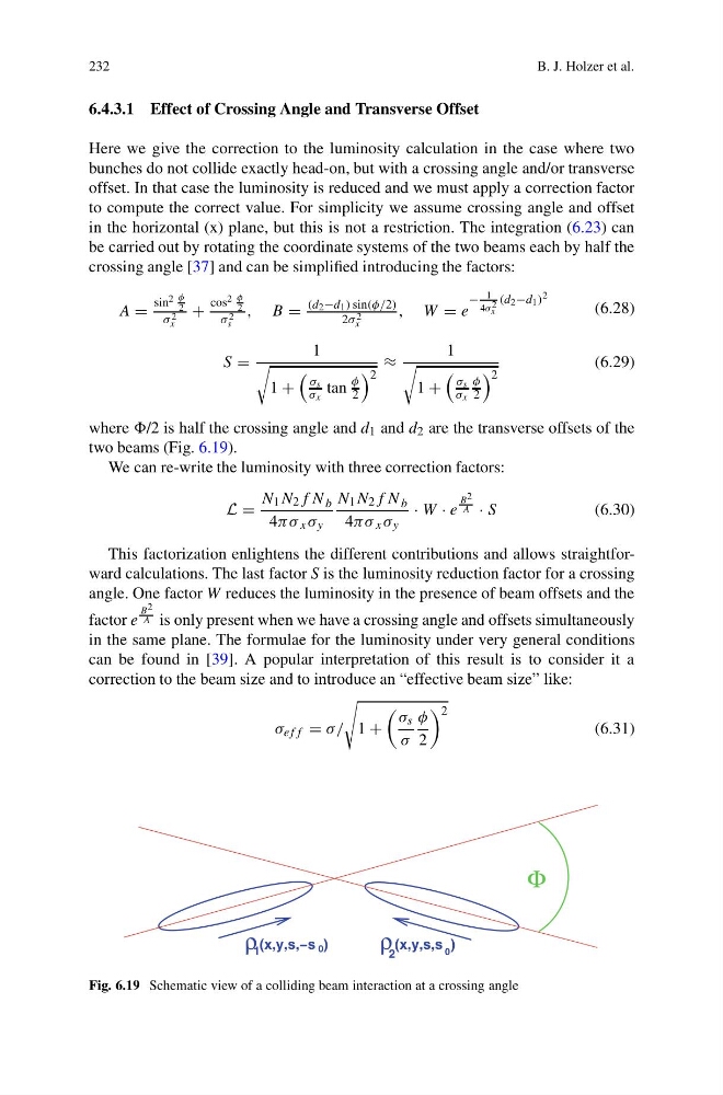
where /2 is half the crossing angle and d 1 and d 2 are the transverse offsets of the
two beams (Fig. 6.19).
We can re-write the luminosity with three correction factors:
L =
N 1 N 2 f N b
4πσ x σ y
N 1 N 2 f N b
4πσ x σ y
· W · e
B 2
A · S
(6.30)
This factorization enlightens the different contributions and allows straightforward calculations. The last factor S is the luminosity reduction factor for a crossing
angle. One factor W reduces the luminosity in the presence of beam offsets and the
factor e
B 2
A is only present when we have a crossing angle and offsets simultaneously
in the same plane. The formulae for the luminosity under very general conditions
can be found in [39]. A popular interpretation of this result is to consider it a
correction to the beam size and to introduce an “effective beam size” like:
σ eff = σ/
1 +
σ s
σ
φ
2
2
(6.31)
(x,y,s,s )
2
ρ
(x,y,s,−s )
1
ρ
0
0
Φ
Fig. 6.19 Schematic view of a colliding beam interaction at a crossing angle
B. J. Holzer et al.
6.4.3.1 Effect of Crossing Angle and Transverse Offset
Here we give the correction to the luminosity calculation in the case where two
bunches do not collide exactly head-on, but with a crossing angle and/or transverse
offset. In that case the luminosity is reduced and we must apply a correction factor
to compute the correct value. For simplicity we assume crossing angle and offset
in the horizontal (x) plane, but this is not a restriction. The integration (6.23) can
be carried out by rotating the coordinate systems of the two beams each by half the
crossing angle [37] and can be simplified introducing the factors:
A =
sin 2 φ
2
σ 2
x
+
cos 2 φ
2
σ 2
s
, B =
(d 2 −d 1 ) sin(φ/2)
2σ 2
x
, W = e
−
1
4σ 2
x
(d 2 −d 1 ) 2
(6.28)
S =
1
1 +
σ s
σ x
tan
φ
2
2
≈
1
1 +
σ s
σ x
φ
2
2
(6.29)
where /2 is half the crossing angle and d 1 and d 2 are the transverse offsets of the
two beams (Fig. 6.19).
We can re-write the luminosity with three correction factors:
L =
N 1 N 2 f N b
4πσ x σ y
N 1 N 2 f N b
4πσ x σ y
· W · e
B 2
A · S
(6.30)
This factorization enlightens the different contributions and allows straightforward calculations. The last factor S is the luminosity reduction factor for a crossing
angle. One factor W reduces the luminosity in the presence of beam offsets and the
factor e
B 2
A is only present when we have a crossing angle and offsets simultaneously
in the same plane. The formulae for the luminosity under very general conditions
can be found in [39]. A popular interpretation of this result is to consider it a
correction to the beam size and to introduce an “effective beam size” like:
σ eff = σ/
1 +
σ s
σ
φ
2
2
(6.31)
(x,y,s,s )
2
ρ
(x,y,s,−s )
1
ρ
0
0
Φ
Fig. 6.19 Schematic view of a colliding beam interaction at a crossing angle