

216
B. J. Holzer et al.
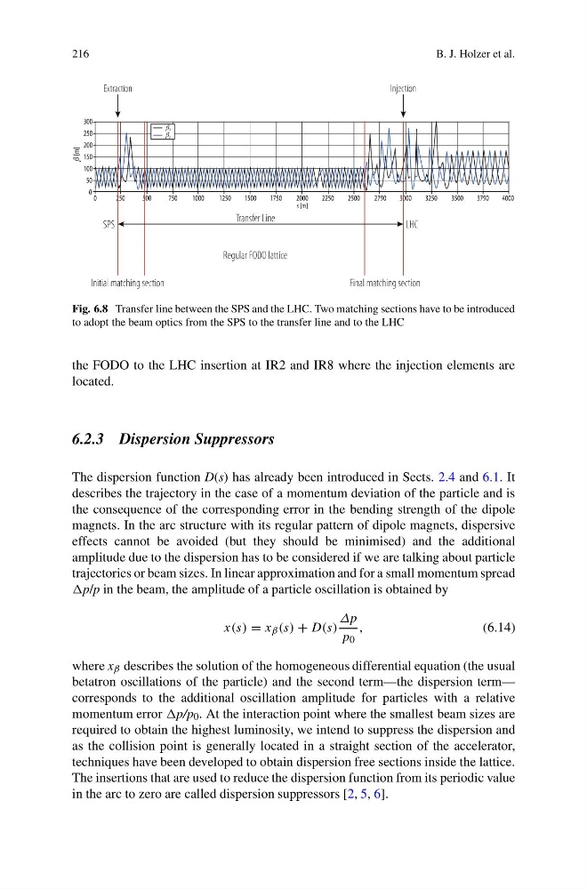
Fig. 6.8 Transfer line between the SPS and the LHC. Two matching sections have to be introduced
to adopt the beam optics from the SPS to the transfer line and to the LHC
the FODO to the LHC insertion at IR2 and IR8 where the injection elements are
located.
6.2.3 Dispersion Suppressors
The dispersion function D(s) has already been introduced in Sects. 2.4 and 6.1. It
describes the trajectory in the case of a momentum deviation of the particle and is
the consequence of the corresponding error in the bending strength of the dipole
magnets. In the arc structure with its regular pattern of dipole magnets, dispersive
effects cannot be avoided (but they should be minimised) and the additional
amplitude due to the dispersion has to be considered if we are talking about particle
trajectories or beam sizes. In linear approximation and for a small momentum spread
in the beam, the amplitude of a particle oscillation is obtained by
x(s) = x β (s) + D(s)
Δp
p 0
,
(6.14)
where x β describes the solution of the homogeneous differential equation (the usual
betatron oscillations of the particle) and the second term—the dispersion term—
corresponds to the additional oscillation amplitude for particles with a relative
momentum error p/p 0 . At the interaction point where the smallest beam sizes are
required to obtain the highest luminosity, we intend to suppress the dispersion and
as the collision point is generally located in a straight section of the accelerator,
techniques have been developed to obtain dispersion free sections inside the lattice.
The insertions that are used to reduce the dispersion function from its periodic value
in the arc to zero are called dispersion suppressors [2, 5, 6].
B. J. Holzer et al.
Fig. 6.8 Transfer line between the SPS and the LHC. Two matching sections have to be introduced
to adopt the beam optics from the SPS to the transfer line and to the LHC
the FODO to the LHC insertion at IR2 and IR8 where the injection elements are
located.
6.2.3 Dispersion Suppressors
The dispersion function D(s) has already been introduced in Sects. 2.4 and 6.1. It
describes the trajectory in the case of a momentum deviation of the particle and is
the consequence of the corresponding error in the bending strength of the dipole
magnets. In the arc structure with its regular pattern of dipole magnets, dispersive
effects cannot be avoided (but they should be minimised) and the additional
amplitude due to the dispersion has to be considered if we are talking about particle
trajectories or beam sizes. In linear approximation and for a small momentum spread
in the beam, the amplitude of a particle oscillation is obtained by
x(s) = x β (s) + D(s)
Δp
p 0
,
(6.14)
where x β describes the solution of the homogeneous differential equation (the usual
betatron oscillations of the particle) and the second term—the dispersion term—
corresponds to the additional oscillation amplitude for particles with a relative
momentum error p/p 0 . At the interaction point where the smallest beam sizes are
required to obtain the highest luminosity, we intend to suppress the dispersion and
as the collision point is generally located in a straight section of the accelerator,
techniques have been developed to obtain dispersion free sections inside the lattice.
The insertions that are used to reduce the dispersion function from its periodic value
in the arc to zero are called dispersion suppressors [2, 5, 6].