

4 Impedance and Collective Effects
125
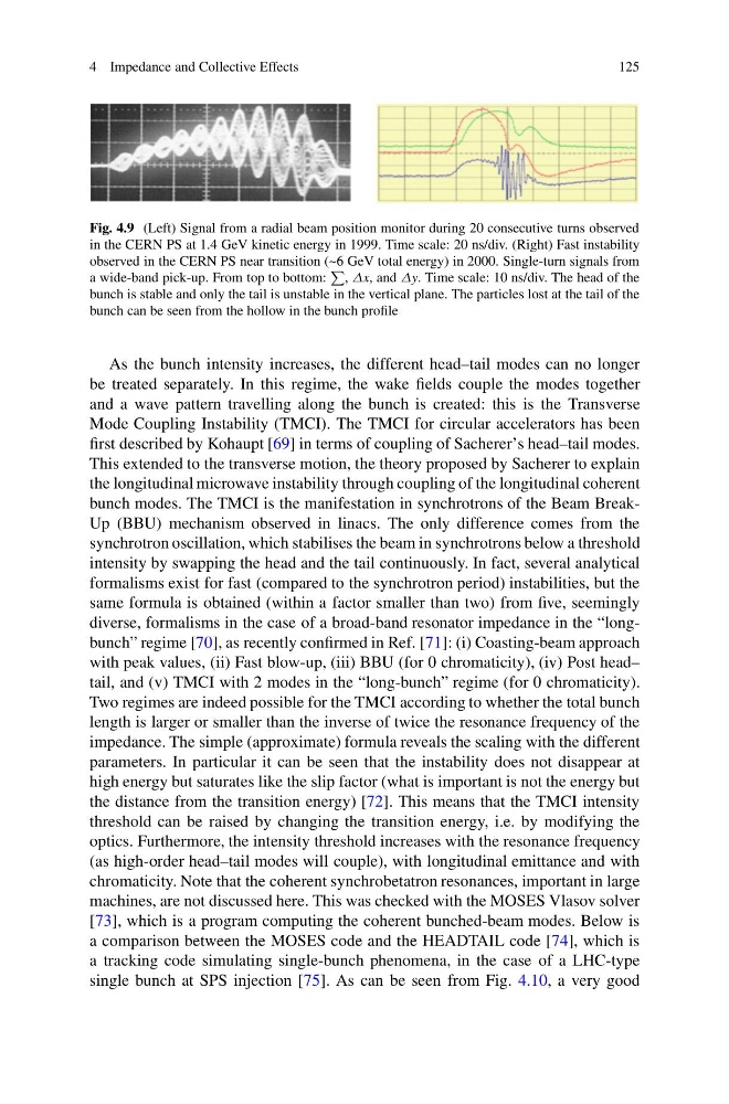
Fig. 4.9 (Left) Signal from a radial beam position monitor during 20 consecutive turns observed
in the CERN PS at 1.4 GeV kinetic energy in 1999. Time scale: 20 ns/div. (Right) Fast instability
observed in the CERN PS near transition (~6 GeV total energy) in 2000. Single-turn signals from
a wide-band pick-up. From top to bottom:
, Δx, and Δy. Time scale: 10 ns/div. The head of the
bunch is stable and only the tail is unstable in the vertical plane. The particles lost at the tail of the
bunch can be seen from the hollow in the bunch profile
As the bunch intensity increases, the different head–tail modes can no longer
be treated separately. In this regime, the wake fields couple the modes together
and a wave pattern travelling along the bunch is created: this is the Transverse
Mode Coupling Instability (TMCI). The TMCI for circular accelerators has been
first described by Kohaupt [69] in terms of coupling of Sacherer’s head–tail modes.
This extended to the transverse motion, the theory proposed by Sacherer to explain
the longitudinal microwave instability through coupling of the longitudinal coherent
bunch modes. The TMCI is the manifestation in synchrotrons of the Beam BreakUp (BBU) mechanism observed in linacs. The only difference comes from the
synchrotron oscillation, which stabilises the beam in synchrotrons below a threshold
intensity by swapping the head and the tail continuously. In fact, several analytical
formalisms exist for fast (compared to the synchrotron period) instabilities, but the
same formula is obtained (within a factor smaller than two) from five, seemingly
diverse, formalisms in the case of a broad-band resonator impedance in the “longbunch” regime [70], as recently confirmed in Ref. [71]: (i) Coasting-beam approach
with peak values, (ii) Fast blow-up, (iii) BBU (for 0 chromaticity), (iv) Post head–
tail, and (v) TMCI with 2 modes in the “long-bunch” regime (for 0 chromaticity).
Two regimes are indeed possible for the TMCI according to whether the total bunch
length is larger or smaller than the inverse of twice the resonance frequency of the
impedance. The simple (approximate) formula reveals the scaling with the different
parameters. In particular it can be seen that the instability does not disappear at
high energy but saturates like the slip factor (what is important is not the energy but
the distance from the transition energy) [72]. This means that the TMCI intensity
threshold can be raised by changing the transition energy, i.e. by modifying the
optics. Furthermore, the intensity threshold increases with the resonance frequency
(as high-order head–tail modes will couple), with longitudinal emittance and with
chromaticity. Note that the coherent synchrobetatron resonances, important in large
machines, are not discussed here. This was checked with the MOSES Vlasov solver
[73], which is a program computing the coherent bunched-beam modes. Below is
a comparison between the MOSES code and the HEADTAIL code [74], which is
a tracking code simulating single-bunch phenomena, in the case of a LHC-type
single bunch at SPS injection [75]. As can be seen from Fig. 4.10, a very good
125
Fig. 4.9 (Left) Signal from a radial beam position monitor during 20 consecutive turns observed
in the CERN PS at 1.4 GeV kinetic energy in 1999. Time scale: 20 ns/div. (Right) Fast instability
observed in the CERN PS near transition (~6 GeV total energy) in 2000. Single-turn signals from
a wide-band pick-up. From top to bottom:
, Δx, and Δy. Time scale: 10 ns/div. The head of the
bunch is stable and only the tail is unstable in the vertical plane. The particles lost at the tail of the
bunch can be seen from the hollow in the bunch profile
As the bunch intensity increases, the different head–tail modes can no longer
be treated separately. In this regime, the wake fields couple the modes together
and a wave pattern travelling along the bunch is created: this is the Transverse
Mode Coupling Instability (TMCI). The TMCI for circular accelerators has been
first described by Kohaupt [69] in terms of coupling of Sacherer’s head–tail modes.
This extended to the transverse motion, the theory proposed by Sacherer to explain
the longitudinal microwave instability through coupling of the longitudinal coherent
bunch modes. The TMCI is the manifestation in synchrotrons of the Beam BreakUp (BBU) mechanism observed in linacs. The only difference comes from the
synchrotron oscillation, which stabilises the beam in synchrotrons below a threshold
intensity by swapping the head and the tail continuously. In fact, several analytical
formalisms exist for fast (compared to the synchrotron period) instabilities, but the
same formula is obtained (within a factor smaller than two) from five, seemingly
diverse, formalisms in the case of a broad-band resonator impedance in the “longbunch” regime [70], as recently confirmed in Ref. [71]: (i) Coasting-beam approach
with peak values, (ii) Fast blow-up, (iii) BBU (for 0 chromaticity), (iv) Post head–
tail, and (v) TMCI with 2 modes in the “long-bunch” regime (for 0 chromaticity).
Two regimes are indeed possible for the TMCI according to whether the total bunch
length is larger or smaller than the inverse of twice the resonance frequency of the
impedance. The simple (approximate) formula reveals the scaling with the different
parameters. In particular it can be seen that the instability does not disappear at
high energy but saturates like the slip factor (what is important is not the energy but
the distance from the transition energy) [72]. This means that the TMCI intensity
threshold can be raised by changing the transition energy, i.e. by modifying the
optics. Furthermore, the intensity threshold increases with the resonance frequency
(as high-order head–tail modes will couple), with longitudinal emittance and with
chromaticity. Note that the coherent synchrobetatron resonances, important in large
machines, are not discussed here. This was checked with the MOSES Vlasov solver
[73], which is a program computing the coherent bunched-beam modes. Below is
a comparison between the MOSES code and the HEADTAIL code [74], which is
a tracking code simulating single-bunch phenomena, in the case of a LHC-type
single bunch at SPS injection [75]. As can be seen from Fig. 4.10, a very good