

124
E. Metral et al.
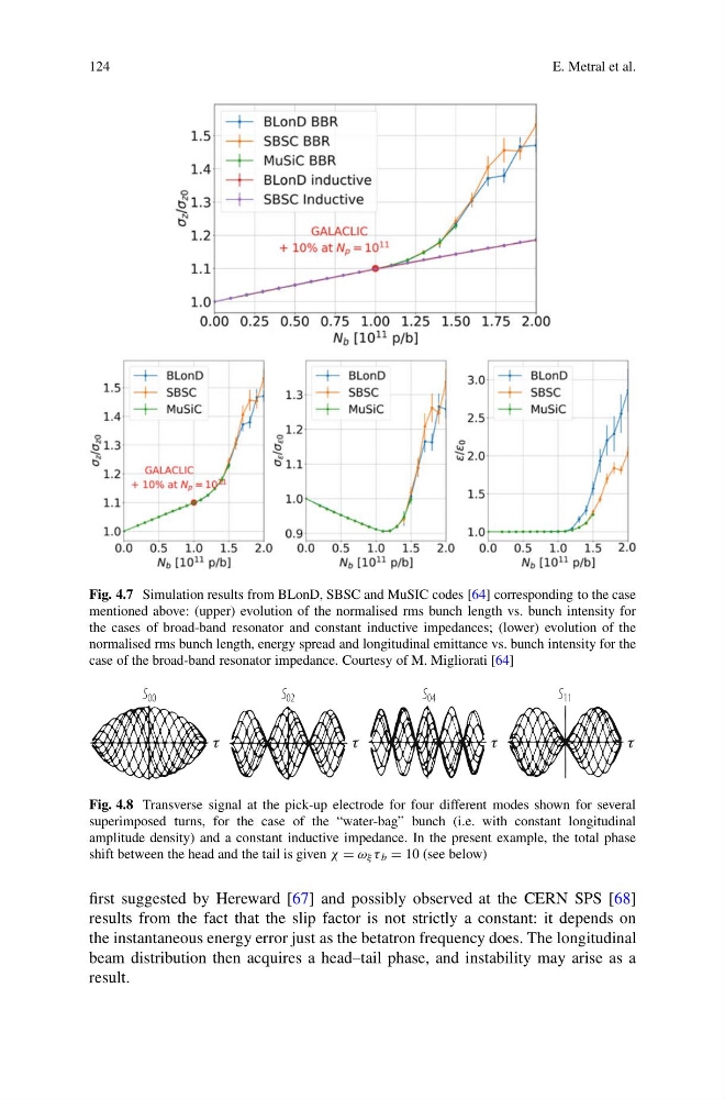
Fig. 4.7 Simulation results from BLonD, SBSC and MuSIC codes [64] corresponding to the case
mentioned above: (upper) evolution of the normalised rms bunch length vs. bunch intensity for
the cases of broad-band resonator and constant inductive impedances; (lower) evolution of the
normalised rms bunch length, energy spread and longitudinal emittance vs. bunch intensity for the
case of the broad-band resonator impedance. Courtesy of M. Migliorati [64]
Fig. 4.8 Transverse signal at the pick-up electrode for four different modes shown for several
superimposed turns, for the case of the “water-bag” bunch (i.e. with constant longitudinal
amplitude density) and a constant inductive impedance. In the present example, the total phase
shift between the head and the tail is given χ = ω ξ τ b = 10 (see below)
first suggested by Hereward [67] and possibly observed at the CERN SPS [68]
results from the fact that the slip factor is not strictly a constant: it depends on
the instantaneous energy error just as the betatron frequency does. The longitudinal
beam distribution then acquires a head–tail phase, and instability may arise as a
result.
E. Metral et al.
Fig. 4.7 Simulation results from BLonD, SBSC and MuSIC codes [64] corresponding to the case
mentioned above: (upper) evolution of the normalised rms bunch length vs. bunch intensity for
the cases of broad-band resonator and constant inductive impedances; (lower) evolution of the
normalised rms bunch length, energy spread and longitudinal emittance vs. bunch intensity for the
case of the broad-band resonator impedance. Courtesy of M. Migliorati [64]
Fig. 4.8 Transverse signal at the pick-up electrode for four different modes shown for several
superimposed turns, for the case of the “water-bag” bunch (i.e. with constant longitudinal
amplitude density) and a constant inductive impedance. In the present example, the total phase
shift between the head and the tail is given χ = ω ξ τ b = 10 (see below)
first suggested by Hereward [67] and possibly observed at the CERN SPS [68]
results from the fact that the slip factor is not strictly a constant: it depends on
the instantaneous energy error just as the betatron frequency does. The longitudinal
beam distribution then acquires a head–tail phase, and instability may arise as a
result.