

3 Continuous Catalytic Processes with Supported Ionic Liquid …
55
0
100
200
300
400
500
600
700
800
900
0
10
20
30
40
50
Time on stream / h
Conversion of butenes / %
70
75
80
85
90
95
100
n-pentanal / %
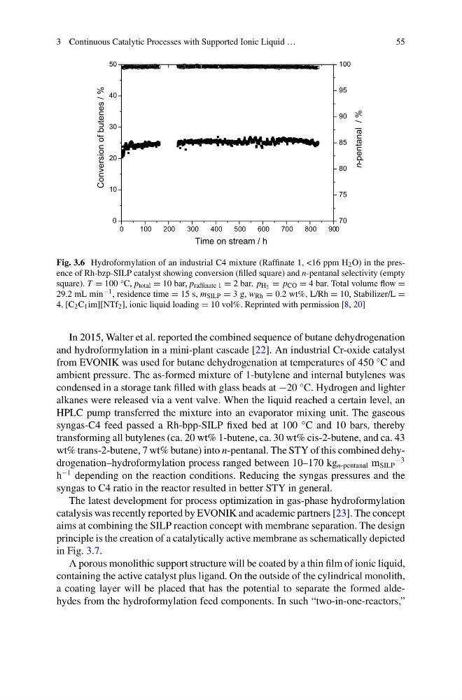
Fig. 3.6 Hydroformylation of an industrial C4 mixture (Raffinate 1, <16 ppm H 2 O) in the presence of Rh-bzp-SILP catalyst showing conversion (filled square) and n-pentanal selectivity (empty
square). T = 100 °C, p total = 10 bar, p raffinate 1 = 2 bar, p H2 = p CO = 4 bar. Total volume flow =
29.2 mL min −1 , residence time = 15 s, m SILP = 3 g, w Rh = 0.2 wt%, L/Rh = 10, Stabilizer/L =
4, [C 2 C 1 im][NTf 2 ], ionic liquid loading = 10 vol%. Reprinted with permission [8, 20]
In 2015, Walter et al. reported the combined sequence of butane dehydrogenation
and hydroformylation in a mini-plant cascade [22]. An industrial Cr-oxide catalyst
from EVONIK was used for butane dehydrogenation at temperatures of 450 °C and
ambient pressure. The as-formed mixture of 1-butylene and internal butylenes was
condensed in a storage tank filled with glass beads at −20 °C. Hydrogen and lighter
alkanes were released via a vent valve. When the liquid reached a certain level, an
HPLC pump transferred the mixture into an evaporator mixing unit. The gaseous
syngas-C4 feed passed a Rh-bpp-SILP fixed bed at 100 °C and 10 bars, thereby
transforming all butylenes (ca. 20 wt% 1-butene, ca. 30 wt% cis-2-butene, and ca. 43
wt% trans-2-butene, 7 wt% butane) into n-pentanal. The STY of this combined dehydrogenation–hydroformylation process ranged between 10–170 kg n-pentanal m SILP
−3
h
−1 depending on the reaction conditions. Reducing the syngas pressures and the
syngas to C4 ratio in the reactor resulted in better STY in general.
The latest development for process optimization in gas-phase hydroformylation
catalysis was recently reported by EVONIK and academic partners [23]. The concept
aims at combining the SILP reaction concept with membrane separation. The design
principle is the creation of a catalytically active membrane as schematically depicted
in Fig. 3.7.
A porous monolithic support structure will be coated by a thin film of ionic liquid,
containing the active catalyst plus ligand. On the outside of the cylindrical monolith,
a coating layer will be placed that has the potential to separate the formed aldehydes from the hydroformylation feed components. In such “two-in-one-reactors,”
55
0
100
200
300
400
500
600
700
800
900
0
10
20
30
40
50
Time on stream / h
Conversion of butenes / %
70
75
80
85
90
95
100
n-pentanal / %
Fig. 3.6 Hydroformylation of an industrial C4 mixture (Raffinate 1, <16 ppm H 2 O) in the presence of Rh-bzp-SILP catalyst showing conversion (filled square) and n-pentanal selectivity (empty
square). T = 100 °C, p total = 10 bar, p raffinate 1 = 2 bar, p H2 = p CO = 4 bar. Total volume flow =
29.2 mL min −1 , residence time = 15 s, m SILP = 3 g, w Rh = 0.2 wt%, L/Rh = 10, Stabilizer/L =
4, [C 2 C 1 im][NTf 2 ], ionic liquid loading = 10 vol%. Reprinted with permission [8, 20]
In 2015, Walter et al. reported the combined sequence of butane dehydrogenation
and hydroformylation in a mini-plant cascade [22]. An industrial Cr-oxide catalyst
from EVONIK was used for butane dehydrogenation at temperatures of 450 °C and
ambient pressure. The as-formed mixture of 1-butylene and internal butylenes was
condensed in a storage tank filled with glass beads at −20 °C. Hydrogen and lighter
alkanes were released via a vent valve. When the liquid reached a certain level, an
HPLC pump transferred the mixture into an evaporator mixing unit. The gaseous
syngas-C4 feed passed a Rh-bpp-SILP fixed bed at 100 °C and 10 bars, thereby
transforming all butylenes (ca. 20 wt% 1-butene, ca. 30 wt% cis-2-butene, and ca. 43
wt% trans-2-butene, 7 wt% butane) into n-pentanal. The STY of this combined dehydrogenation–hydroformylation process ranged between 10–170 kg n-pentanal m SILP
−3
h
−1 depending on the reaction conditions. Reducing the syngas pressures and the
syngas to C4 ratio in the reactor resulted in better STY in general.
The latest development for process optimization in gas-phase hydroformylation
catalysis was recently reported by EVONIK and academic partners [23]. The concept
aims at combining the SILP reaction concept with membrane separation. The design
principle is the creation of a catalytically active membrane as schematically depicted
in Fig. 3.7.
A porous monolithic support structure will be coated by a thin film of ionic liquid,
containing the active catalyst plus ligand. On the outside of the cylindrical monolith,
a coating layer will be placed that has the potential to separate the formed aldehydes from the hydroformylation feed components. In such “two-in-one-reactors,”