

3 Continuous Catalytic Processes with Supported Ionic Liquid …
53
(RCH/RP) process, utilizing a water-soluble Rh-tppts catalyst (see Fig. 3.2), operates
at a STY of 200 kg m
−3 h
−1 for propylene at 120 °C and 50 bar [14]. It should be
noted that the gas-phase process pressure was only 10 bar, while the RCH/RP process
requires 50 bar. These values indicate the potential of a new SILP gas-phase process,
especially considering the transformation from propylene to 1-butylene feedstock due
to better product properties. Mass transport limitations were estimated and found to
be negligible on overall reaction kinetics up to pellet diameters of 2.5 mm [15].
An industrially relevant reaction would be the transformation of internal olefins
in an isomerization–hydroformylation sequence [16–18]. EVONIK reported a
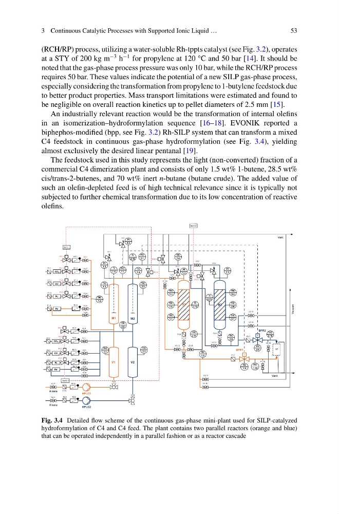
biphephos-modified (bpp, see Fig. 3.2) Rh-SILP system that can transform a mixed
C4 feedstock in continuous gas-phase hydroformylation (see Fig. 3.4), yielding
almost exclusively the desired linear pentanal [19].
The feedstock used in this study represents the light (non-converted) fraction of a
commercial C4 dimerization plant and consists of only 1.5 wt% 1-butene, 28.5 wt%
cis/trans-2-butenes, and 70 wt% inert n-butane (butane crude). The added value of
such an olefin-depleted feed is of high technical relevance since it is typically not
subjected to further chemical transformation due to its low concentration of reactive
olefins.
F
F
F
V1.8
V2.8
V1.9
V2.9
V2.10
V1.10
V1.12
V2.12
V1.3
V1.4
V2.1
V2.2
V1.7
V2.7
SV1.1
SV2.1
SV1.2
SV2.2
H2
Alkene
Alkene
CO
PV1.4
PV2.
2
HPLC1
HPLC2
BPR1
BPR2
V1
V2
R1
R2
M1
M2
Vent
Vacuum
Vent
GC
PV2.1
PV1.3
F
V1.5
He
F
He
V2.16
V1.1
PV1.1
V1.13
V1.11
SeV1.1
PV1.2
V1.6
V2.11
PV1.5
PV2.5
V1.16
V2.15
F1.2
F1.3
F1.4
F2.1
F1.5
F2.5
F1.6
F1.7
F2.6
F2.7
R1.1
R1.2
R1.3
R1.4
R1.5
R2.1
R2.2
R2.3
R1.6
R2.6
TIC
1.1
TIC
2.1
TIC
1.2
TIC
2.2
TIC
1.3
TIC
2.3
TIC
1.4
TIC
2.4
TIC
1.5
TIC
1.6
TIC
1.7
TIC
1.8
TIC
1.9
TIC
2.11
TIC
2.5
TIC
2.6
TIC
2.7
TIC
2.8
TIC
2.9
PIC
1.1
PIC
2.1
PI
1.2
PI
1.3
PI
2.2
PI
2.3
TI
1.11
TI
2.12
TI
1.12
TI
2.13
1
2
V2.6
V2.14
V2.13
V1.14
V1.15
V2.5
SeV2.1
PV2.6
SeV2.2
TIC
1.10
TIC
2.10
F
CO2
F1.1
CO2
F
V2.3
PV2.
3
F2.2
R2.3
CO
F
V2.4
PV2.
4
F2.3
R2.4
H2
F2.4
R2.5
Fig. 3.4 Detailed flow scheme of the continuous gas-phase mini-plant used for SILP-catalyzed
hydroformylation of C4 and C4 feed. The plant contains two parallel reactors (orange and blue)
that can be operated independently in a parallel fashion or as a reactor cascade
53
(RCH/RP) process, utilizing a water-soluble Rh-tppts catalyst (see Fig. 3.2), operates
at a STY of 200 kg m
−3 h
−1 for propylene at 120 °C and 50 bar [14]. It should be
noted that the gas-phase process pressure was only 10 bar, while the RCH/RP process
requires 50 bar. These values indicate the potential of a new SILP gas-phase process,
especially considering the transformation from propylene to 1-butylene feedstock due
to better product properties. Mass transport limitations were estimated and found to
be negligible on overall reaction kinetics up to pellet diameters of 2.5 mm [15].
An industrially relevant reaction would be the transformation of internal olefins
in an isomerization–hydroformylation sequence [16–18]. EVONIK reported a
biphephos-modified (bpp, see Fig. 3.2) Rh-SILP system that can transform a mixed
C4 feedstock in continuous gas-phase hydroformylation (see Fig. 3.4), yielding
almost exclusively the desired linear pentanal [19].
The feedstock used in this study represents the light (non-converted) fraction of a
commercial C4 dimerization plant and consists of only 1.5 wt% 1-butene, 28.5 wt%
cis/trans-2-butenes, and 70 wt% inert n-butane (butane crude). The added value of
such an olefin-depleted feed is of high technical relevance since it is typically not
subjected to further chemical transformation due to its low concentration of reactive
olefins.
F
F
F
V1.8
V2.8
V1.9
V2.9
V2.10
V1.10
V1.12
V2.12
V1.3
V1.4
V2.1
V2.2
V1.7
V2.7
SV1.1
SV2.1
SV1.2
SV2.2
H2
Alkene
Alkene
CO
PV1.4
PV2.
2
HPLC1
HPLC2
BPR1
BPR2
V1
V2
R1
R2
M1
M2
Vent
Vacuum
Vent
GC
PV2.1
PV1.3
F
V1.5
He
F
He
V2.16
V1.1
PV1.1
V1.13
V1.11
SeV1.1
PV1.2
V1.6
V2.11
PV1.5
PV2.5
V1.16
V2.15
F1.2
F1.3
F1.4
F2.1
F1.5
F2.5
F1.6
F1.7
F2.6
F2.7
R1.1
R1.2
R1.3
R1.4
R1.5
R2.1
R2.2
R2.3
R1.6
R2.6
TIC
1.1
TIC
2.1
TIC
1.2
TIC
2.2
TIC
1.3
TIC
2.3
TIC
1.4
TIC
2.4
TIC
1.5
TIC
1.6
TIC
1.7
TIC
1.8
TIC
1.9
TIC
2.11
TIC
2.5
TIC
2.6
TIC
2.7
TIC
2.8
TIC
2.9
PIC
1.1
PIC
2.1
PI
1.2
PI
1.3
PI
2.2
PI
2.3
TI
1.11
TI
2.12
TI
1.12
TI
2.13
1
2
V2.6
V2.14
V2.13
V1.14
V1.15
V2.5
SeV2.1
PV2.6
SeV2.2
TIC
1.10
TIC
2.10
F
CO2
F1.1
CO2
F
V2.3
PV2.
3
F2.2
R2.3
CO
F
V2.4
PV2.
4
F2.3
R2.4
H2
F2.4
R2.5
Fig. 3.4 Detailed flow scheme of the continuous gas-phase mini-plant used for SILP-catalyzed
hydroformylation of C4 and C4 feed. The plant contains two parallel reactors (orange and blue)
that can be operated independently in a parallel fashion or as a reactor cascade