

85
K mo = N s × K and the total resistance is R smo = N s × R s . The current flows into the
series cell arrangement are equal in all components, that is, I Lmo = I L and I omo = I o .
Therefore, the I mo –V mo correlation in the N s arranged cells is denoted by
V
I N R N K
I I
I
I
mo
mo s s
s
L
m o
o
o
= −
+
−
+
log
.
(5.6)
In the same way, when all N p cells are arranged in parallel, the I mo –V mo connection is expressed by [24, 26]
V
I
R
N
K
N I I
N I
N I
mo
mo
S
p
sh L
m o
p o
p o
= −
+
−
+
log
.
(5.7)
Since the photon-generated current is primarily reliant on the photon emission
panel’s relativistic temperature conditions and the solar irradiance, the current could
be computed as follows:
I
G I
K T
V
L
S C
I
cool
mo
=
+ ( )
(5.8)
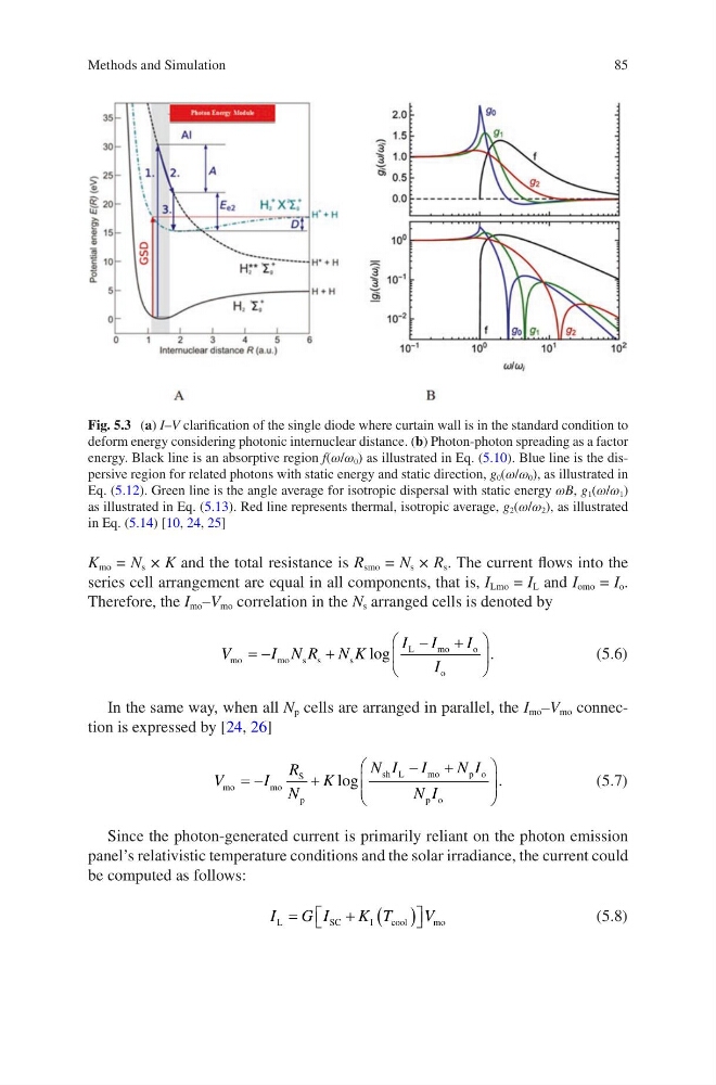
Fig. 5.3 (a) I–V clarification of the single diode where curtain wall is in the standard condition to
deform energy considering photonic internuclear distance. (b) Photon-photon spreading as a factor
energy. Black line is an absorptive region f(ω/ω 0 ) as illustrated in Eq. (5.10). Blue line is the dispersive region for related photons with static energy and static direction, g 0 (ω/ω 0 ), as illustrated in
Eq. (5.12). Green line is the angle average for isotropic dispersal with static energy ωB, g 1 (ω/ω 1 )
as illustrated in Eq. (5.13). Red line represents thermal, isotropic average, g 2 (ω/ω 2 ), as illustrated
in Eq. (5.14) [10, 24, 25]
Methods and Simulation
K mo = N s × K and the total resistance is R smo = N s × R s . The current flows into the
series cell arrangement are equal in all components, that is, I Lmo = I L and I omo = I o .
Therefore, the I mo –V mo correlation in the N s arranged cells is denoted by
V
I N R N K
I I
I
I
mo
mo s s
s
L
m o
o
o
= −
+
−
+
log
.
(5.6)
In the same way, when all N p cells are arranged in parallel, the I mo –V mo connection is expressed by [24, 26]
V
I
R
N
K
N I I
N I
N I
mo
mo
S
p
sh L
m o
p o
p o
= −
+
−
+
log
.
(5.7)
Since the photon-generated current is primarily reliant on the photon emission
panel’s relativistic temperature conditions and the solar irradiance, the current could
be computed as follows:
I
G I
K T
V
L
S C
I
cool
mo
=
+ ( )
(5.8)
Fig. 5.3 (a) I–V clarification of the single diode where curtain wall is in the standard condition to
deform energy considering photonic internuclear distance. (b) Photon-photon spreading as a factor
energy. Black line is an absorptive region f(ω/ω 0 ) as illustrated in Eq. (5.10). Blue line is the dispersive region for related photons with static energy and static direction, g 0 (ω/ω 0 ), as illustrated in
Eq. (5.12). Green line is the angle average for isotropic dispersal with static energy ωB, g 1 (ω/ω 1 )
as illustrated in Eq. (5.13). Red line represents thermal, isotropic average, g 2 (ω/ω 2 ), as illustrated
in Eq. (5.14) [10, 24, 25]
Methods and Simulation