

83
Therefore, the proposed photon model that generates HcP
−
comprises heliumassisted point breaks addressed by the converted current module to be used to cool
a building (Fig. 5.2).
The current–voltage (I–V) features of the photonic structures into the singlediode module are illustrated by
I I I
V I
R
q V I
AkT
= −
− −
+
(
)
+
(
)
L
o
Rs
S
Rs
c
exp
}
,
1
(5.2)
whereby I L stands for the photon generation current, I o stands for the induced
current, and R s is the series resistance. A denotes the diode’s inactive mechanism,
k (= 1.38 × 10
−23
W/m
2
K) represents Boltzmann’s constant, q (= 1.6 × 10
−19
C), and
T c stands for the activated curtain wall temperature.
Consequently, the I–q affiliation in the photonic structure differs within the diode
or induced current, which is given by [21–23]
I I
T
T
qE T
T
KA
o
R s
c
ref
G
ref
c
=
−
3
1
1
exp
.
(5.3)
where IR s is the saturation current, which is determined by solar irradiance speed
and working temperature, and qE G stands for the bandgap energy of the electrons
for each photon cell’s unit area. I–V characteristics of two-diode dissimilar models
are presented in Fig. 5.3.
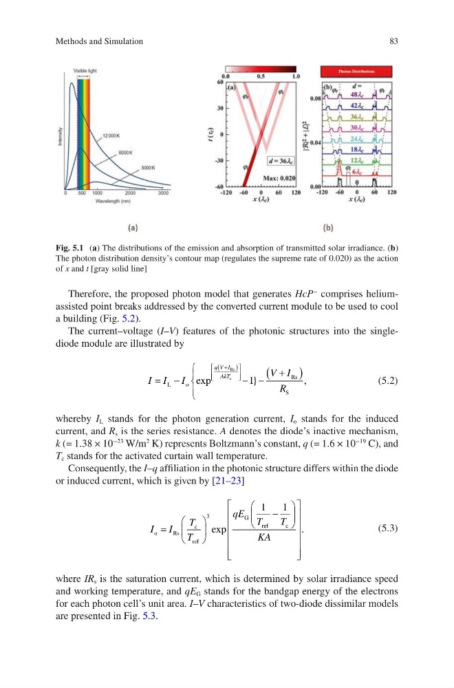
Fig. 5.1 (a) The distributions of the emission and absorption of transmitted solar irradiance. (b)
The photon distribution density’s contour map (regulates the supreme rate of 0.020) as the action
of x and t [gray solid line]
Methods and Simulation
Therefore, the proposed photon model that generates HcP
−
comprises heliumassisted point breaks addressed by the converted current module to be used to cool
a building (Fig. 5.2).
The current–voltage (I–V) features of the photonic structures into the singlediode module are illustrated by
I I I
V I
R
q V I
AkT
= −
− −
+
(
)
+
(
)
L
o
Rs
S
Rs
c
exp
}
,
1
(5.2)
whereby I L stands for the photon generation current, I o stands for the induced
current, and R s is the series resistance. A denotes the diode’s inactive mechanism,
k (= 1.38 × 10
−23
W/m
2
K) represents Boltzmann’s constant, q (= 1.6 × 10
−19
C), and
T c stands for the activated curtain wall temperature.
Consequently, the I–q affiliation in the photonic structure differs within the diode
or induced current, which is given by [21–23]
I I
T
T
qE T
T
KA
o
R s
c
ref
G
ref
c
=
−
3
1
1
exp
.
(5.3)
where IR s is the saturation current, which is determined by solar irradiance speed
and working temperature, and qE G stands for the bandgap energy of the electrons
for each photon cell’s unit area. I–V characteristics of two-diode dissimilar models
are presented in Fig. 5.3.
Fig. 5.1 (a) The distributions of the emission and absorption of transmitted solar irradiance. (b)
The photon distribution density’s contour map (regulates the supreme rate of 0.020) as the action
of x and t [gray solid line]
Methods and Simulation