

371
λ
λ
λ ω λ
d
d
d
q
q
q
d
d
d
q
q
L i
L i
L i
L i
V
Ri
d
dt
V
R
r
r r
m s
r
r r
m s
r
r r
r
r
r
r
r
=
+
=
+
=
+
+
= i i
d
dt
q
q
d
r
r
r
r
+
−
λ ω λ
(17.21)
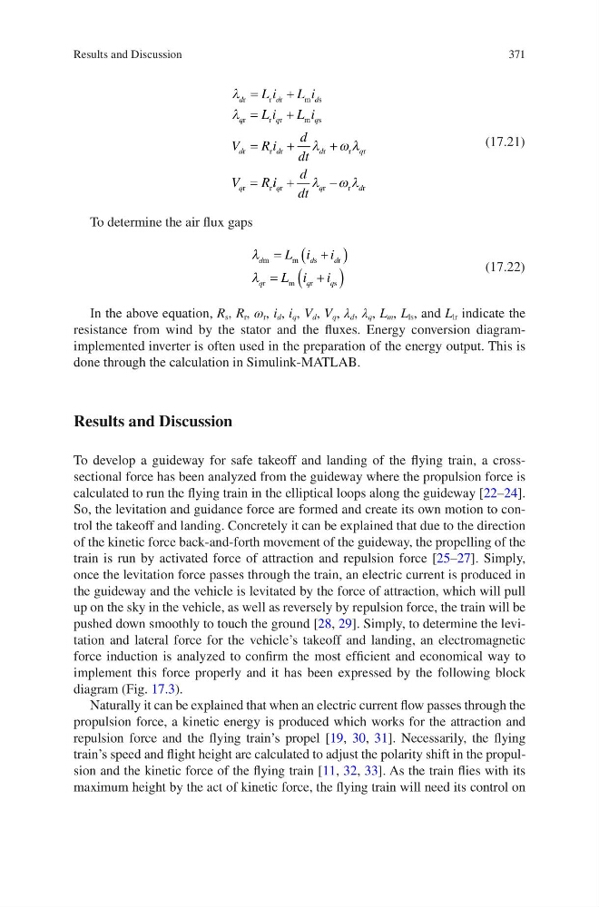
To determine the air flux gaps
λ
λ
d
d
d
q
q
q
L i i
L i i
m
m
s
r
r
m
r
s
=
+
(
)
=
+
(
)
(17.22)
In the above equation, R s , R r , ω r , i d , i q , V d , V q , λ d , λ q , L m , L ls , and L lr indicate the
resistance from wind by the stator and the fluxes. Energy conversion diagramimplemented inverter is often used in the preparation of the energy output. This is
done through the calculation in Simulink-MATLAB.
Results and Discussion
To develop a guideway for safe takeoff and landing of the flying train, a crosssectional force has been analyzed from the guideway where the propulsion force is
calculated to run the flying train in the elliptical loops along the guideway [22–24].
So, the levitation and guidance force are formed and create its own motion to control the takeoff and landing. Concretely it can be explained that due to the direction
of the kinetic force back-and-forth movement of the guideway, the propelling of the
train is run by activated force of attraction and repulsion force [25–27]. Simply,
once the levitation force passes through the train, an electric current is produced in
the guideway and the vehicle is levitated by the force of attraction, which will pull
up on the sky in the vehicle, as well as reversely by repulsion force, the train will be
pushed down smoothly to touch the ground [28, 29]. Simply, to determine the levitation and lateral force for the vehicle’s takeoff and landing, an electromagnetic
force induction is analyzed to confirm the most efficient and economical way to
implement this force properly and it has been expressed by the following block
diagram (Fig. 17.3).
Naturally it can be explained that when an electric current flow passes through the
propulsion force, a kinetic energy is produced which works for the attraction and
repulsion force and the flying train’s propel [19, 30, 31]. Necessarily, the flying
train’s speed and flight height are calculated to adjust the polarity shift in the propulsion and the kinetic force of the flying train [11, 32, 33]. As the train flies with its
maximum height by the act of kinetic force, the flying train will need its control on
Results and Discussion
λ
λ
λ ω λ
d
d
d
q
q
q
d
d
d
q
q
L i
L i
L i
L i
V
Ri
d
dt
V
R
r
r r
m s
r
r r
m s
r
r r
r
r
r
r
r
=
+
=
+
=
+
+
= i i
d
dt
q
q
d
r
r
r
r
+
−
λ ω λ
(17.21)
To determine the air flux gaps
λ
λ
d
d
d
q
q
q
L i i
L i i
m
m
s
r
r
m
r
s
=
+
(
)
=
+
(
)
(17.22)
In the above equation, R s , R r , ω r , i d , i q , V d , V q , λ d , λ q , L m , L ls , and L lr indicate the
resistance from wind by the stator and the fluxes. Energy conversion diagramimplemented inverter is often used in the preparation of the energy output. This is
done through the calculation in Simulink-MATLAB.
Results and Discussion
To develop a guideway for safe takeoff and landing of the flying train, a crosssectional force has been analyzed from the guideway where the propulsion force is
calculated to run the flying train in the elliptical loops along the guideway [22–24].
So, the levitation and guidance force are formed and create its own motion to control the takeoff and landing. Concretely it can be explained that due to the direction
of the kinetic force back-and-forth movement of the guideway, the propelling of the
train is run by activated force of attraction and repulsion force [25–27]. Simply,
once the levitation force passes through the train, an electric current is produced in
the guideway and the vehicle is levitated by the force of attraction, which will pull
up on the sky in the vehicle, as well as reversely by repulsion force, the train will be
pushed down smoothly to touch the ground [28, 29]. Simply, to determine the levitation and lateral force for the vehicle’s takeoff and landing, an electromagnetic
force induction is analyzed to confirm the most efficient and economical way to
implement this force properly and it has been expressed by the following block
diagram (Fig. 17.3).
Naturally it can be explained that when an electric current flow passes through the
propulsion force, a kinetic energy is produced which works for the attraction and
repulsion force and the flying train’s propel [19, 30, 31]. Necessarily, the flying
train’s speed and flight height are calculated to adjust the polarity shift in the propulsion and the kinetic force of the flying train [11, 32, 33]. As the train flies with its
maximum height by the act of kinetic force, the flying train will need its control on
Results and Discussion