

370
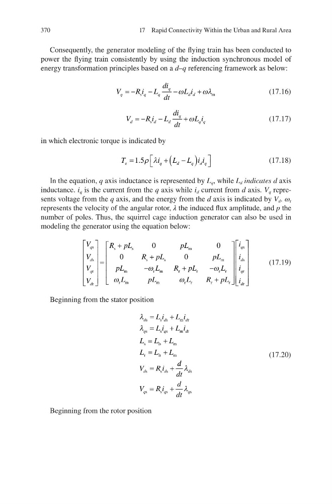
Consequently, the generator modeling of the flying train has been conducted to
power the flying train consistently by using the induction synchronous model of
energy transformation principles based on a d–q referencing framework as below:
V
Ri L
di
dt
L i
q
q
q
q
d d
= −
−
−
+
s
m
ω
ωλ
(17.16)
V
Ri L
di
dt
L i
d
d
d
q
q q
= −
−
+
s
ω
(17.17)
in which electronic torque is indicated by
T
i
L L i i
q
d
q d q
e =
+
−
(
)
1 5
. ρ λ
(17.18)
In the equation, q axis inductance is represented by L q , while L d indicates d axis
inductance. i q is the current from the q axis while i d current from d axis. V q represents voltage from the q axis, and the energy from the d axis is indicated by V d . ω r
represents the velocity of the angular rotor, λ the induced flux amplitude, and p the
number of poles. Thus, the squirrel cage induction generator can also be used in
modeling the generator using the equation below:
V
V
V
V
R pL
p L
R pL
p L
pL
L
R
q
d
q
d
s
s
r
r
s
s
m
s
s
m
m
rm
=
+
+
−
0
0
0
0
ω
r r
r
r r
r m
m
r r
r
r
s
s
r
r
+
−
+
pL
L
L
p L
L
R pL
i
i
i
i
q
d
q
d
ω
ω
ω
(17.19)
Beginning from the stator position
λ
λ
d
d
d
q
q
d
d
d
L i
L i
L i
L i
L L L
L L L
V
Ri
s
s s
m r
s
s s
m r
s
l s
m
r
l r
m
s
s s
=
+
=
+
= +
= +
=
+
d d
dt
V
Ri
d
dt
d
q
q
q
λ
λ
s
s
s s
s
=
+
(17.20)
Beginning from the rotor position
17 Rapid Connectivity Within the Urban and Rural Area
Consequently, the generator modeling of the flying train has been conducted to
power the flying train consistently by using the induction synchronous model of
energy transformation principles based on a d–q referencing framework as below:
V
Ri L
di
dt
L i
q
q
q
q
d d
= −
−
−
+
s
m
ω
ωλ
(17.16)
V
Ri L
di
dt
L i
d
d
d
q
q q
= −
−
+
s
ω
(17.17)
in which electronic torque is indicated by
T
i
L L i i
q
d
q d q
e =
+
−
(
)
1 5
. ρ λ
(17.18)
In the equation, q axis inductance is represented by L q , while L d indicates d axis
inductance. i q is the current from the q axis while i d current from d axis. V q represents voltage from the q axis, and the energy from the d axis is indicated by V d . ω r
represents the velocity of the angular rotor, λ the induced flux amplitude, and p the
number of poles. Thus, the squirrel cage induction generator can also be used in
modeling the generator using the equation below:
V
V
V
V
R pL
p L
R pL
p L
pL
L
R
q
d
q
d
s
s
r
r
s
s
m
s
s
m
m
rm
=
+
+
−
0
0
0
0
ω
r r
r
r r
r m
m
r r
r
r
s
s
r
r
+
−
+
pL
L
L
p L
L
R pL
i
i
i
i
q
d
q
d
ω
ω
ω
(17.19)
Beginning from the stator position
λ
λ
d
d
d
q
q
d
d
d
L i
L i
L i
L i
L L L
L L L
V
Ri
s
s s
m r
s
s s
m r
s
l s
m
r
l r
m
s
s s
=
+
=
+
= +
= +
=
+
d d
dt
V
Ri
d
dt
d
q
q
q
λ
λ
s
s
s s
s
=
+
(17.20)
Beginning from the rotor position
17 Rapid Connectivity Within the Urban and Rural Area