

368
G
K
i t
h
K
y k
k
z k t
k z
,
,
,
=
( )
( )
0
2
(17.6)
G
K
i t
h
K
y k
k
z k t
y k
,
,
,
=
( )
−
(
)
( )
0
2
1
(17.7)
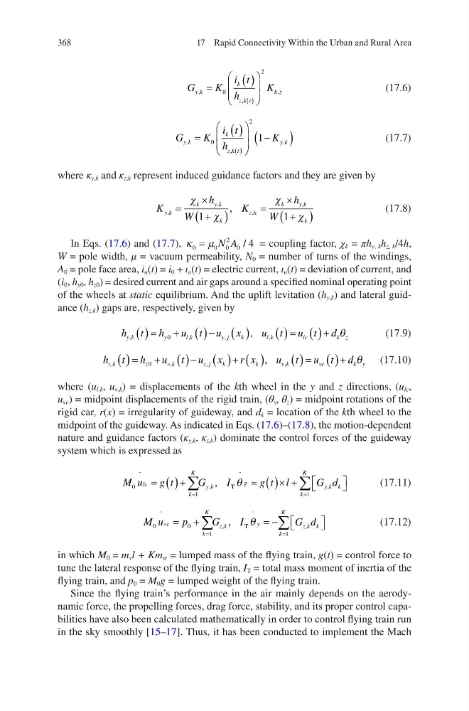
where κ y,k and κ z,k represent induced guidance factors and they are given by
K
h
W
K
h
W
y k
k
yk
k
z k
k
yk
k
,
,
,
,
,
=
×
+
(
)
=
×
+
(
)
χ
χ
χ
χ
1
1
(17.8)
In Eqs. (17.6) and (17.7), κ µ
0
0 0
2
0 4
= N A / = coupling factor, χ k = πh y, k h z, k /4h,
W = pole width, μ = vacuum permeability, N 0 = number of turns of the windings,
A 0 = pole face area, i n (t) = i 0 + ι n (t) = electric current, ι n (t) = deviation of current, and
(i 0 , h y0 , h z0 ) = desired current and air gaps around a specified nominal operating point
of the wheels at static equilibrium. And the uplift levitation (h y,k ) and lateral guidance (h z,k ) gaps are, respectively, given by
h t h
u t u x
u t u t d
y k
y
lk
y j
k
l k
lc
k z
,
,
,
,
,
( ) = + ( )− ( )
( ) = ( )+
0
θ
(17.9)
h t h
u t u x
r x
u t u t d
z k
z
vk
z j
k
k
v k
v c
k y
,
,
,
,
,
( ) = + ( )− ( )+ ( )
( ) = ( )+
0
θ
(17.10)
where (u l,k , u v,k ) = displacements of the kth wheel in the y and z directions, (u lc ,
u vc ) = midpoint displacements of the rigid train, (θ y , θ z ) = midpoint rotations of the
rigid car, r(x) = irregularity of guideway, and d k = location of the kth wheel to the
midpoint of the guideway. As indicated in Eqs. (17.6)–(17.8), the motion-dependent
nature and guidance factors (κ y,k , κ z,k ) dominate the control forces of the guideway
system which is expressed as
M u
g t
G
I
g t l
G d
lc
k
K
y k
Z
k
K
y k k
0
1
1
¨
,
¨
,
,
= ( )+
= ( )× +
=
=
∑
∑
T θ
(17.11)
M u
p
G
I
G d
vc
k
K
z k
y
k
K
z k k
0
0
1
1
¨
,
¨
,
,
= +
= −
=
=
∑
∑
T θ
(17.12)
in which M 0 = m v l + Km w = lumped mass of the flying train, g(t) = control force to
tune the lateral response of the flying train, I T = total mass moment of inertia of the
flying train, and p 0 = M 0 g = lumped weight of the flying train.
Since the flying train’s performance in the air mainly depends on the aerodynamic force, the propelling forces, drag force, stability, and its proper control capabilities have also been calculated mathematically in order to control flying train run
in the sky smoothly [15–17]. Thus, it has been conducted to implement the Mach
17 Rapid Connectivity Within the Urban and Rural Area
G
K
i t
h
K
y k
k
z k t
k z
,
,
,
=
( )
( )
0
2
(17.6)
G
K
i t
h
K
y k
k
z k t
y k
,
,
,
=
( )
−
(
)
( )
0
2
1
(17.7)
where κ y,k and κ z,k represent induced guidance factors and they are given by
K
h
W
K
h
W
y k
k
yk
k
z k
k
yk
k
,
,
,
,
,
=
×
+
(
)
=
×
+
(
)
χ
χ
χ
χ
1
1
(17.8)
In Eqs. (17.6) and (17.7), κ µ
0
0 0
2
0 4
= N A / = coupling factor, χ k = πh y, k h z, k /4h,
W = pole width, μ = vacuum permeability, N 0 = number of turns of the windings,
A 0 = pole face area, i n (t) = i 0 + ι n (t) = electric current, ι n (t) = deviation of current, and
(i 0 , h y0 , h z0 ) = desired current and air gaps around a specified nominal operating point
of the wheels at static equilibrium. And the uplift levitation (h y,k ) and lateral guidance (h z,k ) gaps are, respectively, given by
h t h
u t u x
u t u t d
y k
y
lk
y j
k
l k
lc
k z
,
,
,
,
,
( ) = + ( )− ( )
( ) = ( )+
0
θ
(17.9)
h t h
u t u x
r x
u t u t d
z k
z
vk
z j
k
k
v k
v c
k y
,
,
,
,
,
( ) = + ( )− ( )+ ( )
( ) = ( )+
0
θ
(17.10)
where (u l,k , u v,k ) = displacements of the kth wheel in the y and z directions, (u lc ,
u vc ) = midpoint displacements of the rigid train, (θ y , θ z ) = midpoint rotations of the
rigid car, r(x) = irregularity of guideway, and d k = location of the kth wheel to the
midpoint of the guideway. As indicated in Eqs. (17.6)–(17.8), the motion-dependent
nature and guidance factors (κ y,k , κ z,k ) dominate the control forces of the guideway
system which is expressed as
M u
g t
G
I
g t l
G d
lc
k
K
y k
Z
k
K
y k k
0
1
1
¨
,
¨
,
,
= ( )+
= ( )× +
=
=
∑
∑
T θ
(17.11)
M u
p
G
I
G d
vc
k
K
z k
y
k
K
z k k
0
0
1
1
¨
,
¨
,
,
= +
= −
=
=
∑
∑
T θ
(17.12)
in which M 0 = m v l + Km w = lumped mass of the flying train, g(t) = control force to
tune the lateral response of the flying train, I T = total mass moment of inertia of the
flying train, and p 0 = M 0 g = lumped weight of the flying train.
Since the flying train’s performance in the air mainly depends on the aerodynamic force, the propelling forces, drag force, stability, and its proper control capabilities have also been calculated mathematically in order to control flying train run
in the sky smoothly [15–17]. Thus, it has been conducted to implement the Mach
17 Rapid Connectivity Within the Urban and Rural Area