

367
mu
c u
EI u
p
G i h
x t
z j
z z j
z z j
k
K
z k
k zk
j
k
¨
,
,
¨
,
,
,
( )
+
+
= −
(
)
=
∑
0
1
,
,
ϕ
(17.2)
and
ϕ
δ
j
k
k
k
k
x t
x x H t t
j
L
v
H t t
jL
v
,
( )= −
(
)
− −
−
( )
−
− −
1
(17.3)
together with the following boundary conditions with lateral (y direction) support
movements:
u
t u t
u L t u t
EI u
t EI u
y j
yj
y j
yjL
z z j
z z j
,
,
¤
,
¤
,
,
,
0
0
0
,
,
,
( )= ( )
( )= ( )
( )=
L L t
,
( )= 0
(17.4)
u
t u L t
EI u
t EI u L t
z j
z j
y y j
y y j
,
,
¤
,
¤
,
0
0
0
0
,
,
,
,
( )= ( )=
( )=
( )=
(17.5)
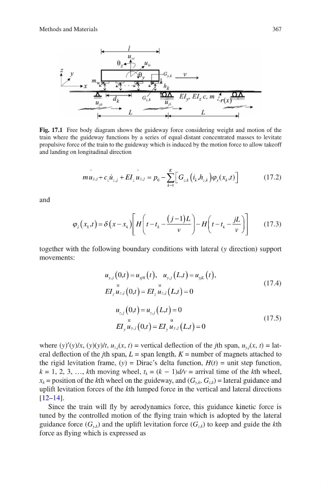
where (y)′(y)/x, (y)(y)/t, u z,j (x, t) = vertical deflection of the jth span, u y,j (x, t) = lateral deflection of the jth span, L = span length, K = number of magnets attached to
the rigid levitation frame, (y) = Dirac’s delta function, H(t) = unit step function,
k = 1, 2, 3, …, kth moving wheel, t k = (k − 1)d/v = arrival time of the kth wheel,
x k = position of the kth wheel on the guideway, and (G y,k , G z,k ) = lateral guidance and
uplift levitation forces of the kth lumped force in the vertical and lateral directions
[12–14].
Since the train will fly by aerodynamics force, this guidance kinetic force is
tuned by the controlled motion of the flying train which is adopted by the lateral
guidance force (G y,k ) and the uplift levitation force (G z,k ) to keep and guide the kth
force as flying which is expressed as
Fig. 17.1 Free body diagram shows the guideway force considering weight and motion of the
train where the guideway functions by a series of equal-distant concentrated masses to levitate
propulsive force of the train to the guideway which is induced by the motion force to allow takeoff
and landing on longitudinal direction
Methods and Materials
mu
c u
EI u
p
G i h
x t
z j
z z j
z z j
k
K
z k
k zk
j
k
¨
,
,
¨
,
,
,
( )
+
+
= −
(
)
=
∑
0
1
,
,
ϕ
(17.2)
and
ϕ
δ
j
k
k
k
k
x t
x x H t t
j
L
v
H t t
jL
v
,
( )= −
(
)
− −
−
( )
−
− −
1
(17.3)
together with the following boundary conditions with lateral (y direction) support
movements:
u
t u t
u L t u t
EI u
t EI u
y j
yj
y j
yjL
z z j
z z j
,
,
¤
,
¤
,
,
,
0
0
0
,
,
,
( )= ( )
( )= ( )
( )=
L L t
,
( )= 0
(17.4)
u
t u L t
EI u
t EI u L t
z j
z j
y y j
y y j
,
,
¤
,
¤
,
0
0
0
0
,
,
,
,
( )= ( )=
( )=
( )=
(17.5)
where (y)′(y)/x, (y)(y)/t, u z,j (x, t) = vertical deflection of the jth span, u y,j (x, t) = lateral deflection of the jth span, L = span length, K = number of magnets attached to
the rigid levitation frame, (y) = Dirac’s delta function, H(t) = unit step function,
k = 1, 2, 3, …, kth moving wheel, t k = (k − 1)d/v = arrival time of the kth wheel,
x k = position of the kth wheel on the guideway, and (G y,k , G z,k ) = lateral guidance and
uplift levitation forces of the kth lumped force in the vertical and lateral directions
[12–14].
Since the train will fly by aerodynamics force, this guidance kinetic force is
tuned by the controlled motion of the flying train which is adopted by the lateral
guidance force (G y,k ) and the uplift levitation force (G z,k ) to keep and guide the kth
force as flying which is expressed as
Fig. 17.1 Free body diagram shows the guideway force considering weight and motion of the
train where the guideway functions by a series of equal-distant concentrated masses to levitate
propulsive force of the train to the guideway which is induced by the motion force to allow takeoff
and landing on longitudinal direction
Methods and Materials