

357
Here, K is as a constant
§
©
¨
·
¹
¸
AkT
q
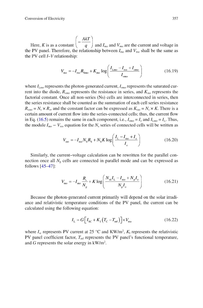
and I mo and V mo are the current and voltage in
the PV panel. Therefore, the relationship between I mo and V mo shall be the same as
the PV cell I–V relationship:
V
I R
K
I
I
I
I
mo
mo Smo
m o
Lmo
m o
o mo
omo
§
©
¨
·
¹
¸
log
(16.19)
where I Lmo represents the photon-generated current, I omo represents the saturated current into the diode, R smo represents the resistance in series, and K mo represents the
factorial constant. Once all non-series (Ns) cells are interconnected in series, then
the series resistance shall be counted as the summation of each cell series resistance
R smo = N s × R s , and the constant factor can be expressed as K mo = N s × K. There is a
certain amount of current flow into the series-connected cells; thus, the current flow
in Eq. (16.5) remains the same in each component, i.e., I omo = I o and I Lmo = I L . Thus,
the module I mo − V mo equation for the N s series of connected cells will be written as
V
I N R N K
I I
I
I
mo
mo S S
S
L
m o
o
o
§
©
¨
·
¹
¸
log
(16.20)
Similarly, the current–voltage calculation can be rewritten for the parallel connection once all N p cells are connected in parallel mode and can be expressed as
follows [45–47]:
V
I
R
N
K
N I I
N I
N I
mo
mo
s
p
sh L
m o
p o
p o
§
©
¨ ¨
·
¹
¸ ¸
log
(16.21)
Because the photon-generated current primarily will depend on the solar irradiance and relativistic temperature conditions of the PV panel, the current can be
calculated using the following equation:
I
G I
K T T
V
L
S C
I
C
r ef
mo
ª ¬
º ¼ u
(16.22)
where I sc represents PV current at 25 °C and KW/m
2
, K I represents the relativistic
PV panel coefficient factor, T ref represents the PV panel’s functional temperature,
and G represents the solar energy in kW/m
2
.
Conversion of Electricity
Here, K is as a constant
§
©
¨
·
¹
¸
AkT
q
and I mo and V mo are the current and voltage in
the PV panel. Therefore, the relationship between I mo and V mo shall be the same as
the PV cell I–V relationship:
V
I R
K
I
I
I
I
mo
mo Smo
m o
Lmo
m o
o mo
omo
§
©
¨
·
¹
¸
log
(16.19)
where I Lmo represents the photon-generated current, I omo represents the saturated current into the diode, R smo represents the resistance in series, and K mo represents the
factorial constant. Once all non-series (Ns) cells are interconnected in series, then
the series resistance shall be counted as the summation of each cell series resistance
R smo = N s × R s , and the constant factor can be expressed as K mo = N s × K. There is a
certain amount of current flow into the series-connected cells; thus, the current flow
in Eq. (16.5) remains the same in each component, i.e., I omo = I o and I Lmo = I L . Thus,
the module I mo − V mo equation for the N s series of connected cells will be written as
V
I N R N K
I I
I
I
mo
mo S S
S
L
m o
o
o
§
©
¨
·
¹
¸
log
(16.20)
Similarly, the current–voltage calculation can be rewritten for the parallel connection once all N p cells are connected in parallel mode and can be expressed as
follows [45–47]:
V
I
R
N
K
N I I
N I
N I
mo
mo
s
p
sh L
m o
p o
p o
§
©
¨ ¨
·
¹
¸ ¸
log
(16.21)
Because the photon-generated current primarily will depend on the solar irradiance and relativistic temperature conditions of the PV panel, the current can be
calculated using the following equation:
I
G I
K T T
V
L
S C
I
C
r ef
mo
ª ¬
º ¼ u
(16.22)
where I sc represents PV current at 25 °C and KW/m
2
, K I represents the relativistic
PV panel coefficient factor, T ref represents the PV panel’s functional temperature,
and G represents the solar energy in kW/m
2
.
Conversion of Electricity