

217
electric energy. Hence, the efficient mechanism of the gearbox of this PMSG plays
a vivacious role in converting the electrical energy to DC current, and it is quantified
by the d–q synchronous voltage equation as
The electronic torque is given by
In the above equation, L q represents the q axis mutual induction, L d is considered
as the d axis inductor, i q represents the q axis flow of electricity, i d represents the d
axis flow of electricity, V q represents the q axis energy, V d denotes the d axis energy,
ω r represents the range of speed of rotor, and λ represents the maximum extent of
the oscillation of the induced flux. P is the quantity of pairs of poles. The demonstration of the dynamic modeling of wind simplifies the electronic torque, as illustrated in the equation below:
The equation that expresses the stator side is
A simplified form of the above equation is
If an air gas flux leaks into the generation, the equation is further simplified to
where R s , R r , L m , L ls , L lr , ω r , i d , i q , V d , V q , λ d , and λ q represent the stator resistance from
one end to another, motor resistance from one end to another, self-inductance of an
inductor with magnetic core, stator leakage inductance, rotor outflow inductance,
electrical rotor angular velocity, electric flow, energy, and fluxes correspondingly of
the d–q model [17]. Then the net productivity power and rotating force of turbine
(T t ) in terms of gyratory velocity can be attained by the following equations:
The fitting equation below expresses the power constant (C p ), which is a discipline that is not linear:
with
In conclusion, an energy transformation circuit diagram processes the output of
the wind energy generator module through the implementation of the converter of
Simulink power systems. Volt that assists in powering the vehicle is the result of
what is calculated as the result of the circuit mode electricity generation (Fig. 11.10).
Generator Modeling
One of the two between initiation and asynchronous dynamo can be applicable in
the WT schemes. Adjustable velocity straight-driven multipole perpetual magnet
synchronous dynamos (PMSGs) are similarly expansively applicable in airstreamdriven energy schemes since they have higher competence, subordinate weight,
cheap upkeep, and stress-free workability and since they do not necessitate a responsive and attracting flow of electricity. The existence of a gearbox in variable- velocity
WTs results in an additional encumbrance of fee and upkeep. Exhausting a straightdriven PMSG does both the increasing of consistency and decreasing of the mass of
the nacelle.
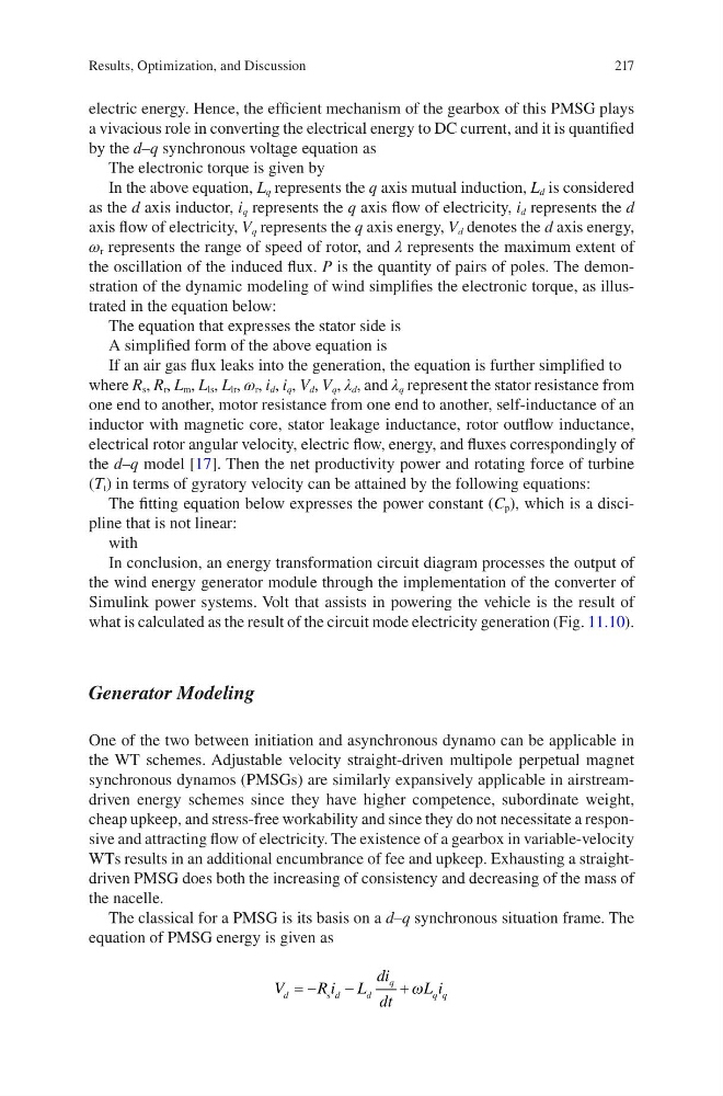
The classical for a PMSG is its basis on a d–q synchronous situation frame. The
equation of PMSG energy is given as
V
Ri L
di
dt
L i
d
d
d
q
q q
= −
−
+
s
ω
Results, Optimization, and Discussion
electric energy. Hence, the efficient mechanism of the gearbox of this PMSG plays
a vivacious role in converting the electrical energy to DC current, and it is quantified
by the d–q synchronous voltage equation as
The electronic torque is given by
In the above equation, L q represents the q axis mutual induction, L d is considered
as the d axis inductor, i q represents the q axis flow of electricity, i d represents the d
axis flow of electricity, V q represents the q axis energy, V d denotes the d axis energy,
ω r represents the range of speed of rotor, and λ represents the maximum extent of
the oscillation of the induced flux. P is the quantity of pairs of poles. The demonstration of the dynamic modeling of wind simplifies the electronic torque, as illustrated in the equation below:
The equation that expresses the stator side is
A simplified form of the above equation is
If an air gas flux leaks into the generation, the equation is further simplified to
where R s , R r , L m , L ls , L lr , ω r , i d , i q , V d , V q , λ d , and λ q represent the stator resistance from
one end to another, motor resistance from one end to another, self-inductance of an
inductor with magnetic core, stator leakage inductance, rotor outflow inductance,
electrical rotor angular velocity, electric flow, energy, and fluxes correspondingly of
the d–q model [17]. Then the net productivity power and rotating force of turbine
(T t ) in terms of gyratory velocity can be attained by the following equations:
The fitting equation below expresses the power constant (C p ), which is a discipline that is not linear:
with
In conclusion, an energy transformation circuit diagram processes the output of
the wind energy generator module through the implementation of the converter of
Simulink power systems. Volt that assists in powering the vehicle is the result of
what is calculated as the result of the circuit mode electricity generation (Fig. 11.10).
Generator Modeling
One of the two between initiation and asynchronous dynamo can be applicable in
the WT schemes. Adjustable velocity straight-driven multipole perpetual magnet
synchronous dynamos (PMSGs) are similarly expansively applicable in airstreamdriven energy schemes since they have higher competence, subordinate weight,
cheap upkeep, and stress-free workability and since they do not necessitate a responsive and attracting flow of electricity. The existence of a gearbox in variable- velocity
WTs results in an additional encumbrance of fee and upkeep. Exhausting a straightdriven PMSG does both the increasing of consistency and decreasing of the mass of
the nacelle.
The classical for a PMSG is its basis on a d–q synchronous situation frame. The
equation of PMSG energy is given as
V
Ri L
di
dt
L i
d
d
d
q
q q
= −
−
+
s
ω
Results, Optimization, and Discussion