

213
An analysis of the electromagnetic torque implies that a predefined power speed
plays a crucial role in trailing the extreme power point into the rotor to convert the
wind into energy computation of MPPT control. The calculation of MPPT, which
was done, had the aim of confirming this stator active power. Thus, the achieving of
the maximum power cofactor depicted that the optimum electromagnetic torque
deduced from MPPT is by determination of the rapidity of the shaft of the winddriven turbine. Since the control of the MPPT revealed the effectiveness of the
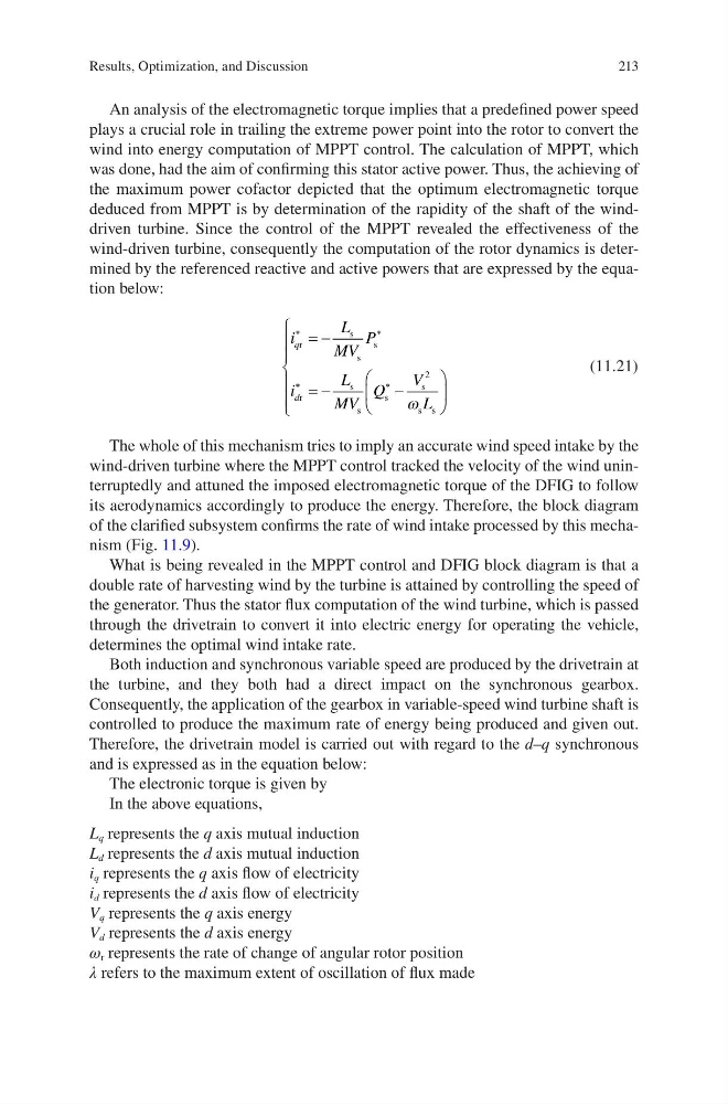
wind-driven turbine, consequently the computation of the rotor dynamics is determined by the referenced reactive and active powers that are expressed by the equation below:
i
L
MV
P
i
L
MV
Q
V
L
q
d
r
s
s
s
r
s
s
s
s
s s
∗
∗
∗
∗
= −
= −
−
2
ω
(11.21)
The whole of this mechanism tries to imply an accurate wind speed intake by the
wind-driven turbine where the MPPT control tracked the velocity of the wind uninterruptedly and attuned the imposed electromagnetic torque of the DFIG to follow
its aerodynamics accordingly to produce the energy. Therefore, the block diagram
of the clarified subsystem confirms the rate of wind intake processed by this mechanism (Fig. 11.9).
What is being revealed in the MPPT control and DFIG block diagram is that a
double rate of harvesting wind by the turbine is attained by controlling the speed of
the generator. Thus the stator flux computation of the wind turbine, which is passed
through the drivetrain to convert it into electric energy for operating the vehicle,
determines the optimal wind intake rate.
Both induction and synchronous variable speed are produced by the drivetrain at
the turbine, and they both had a direct impact on the synchronous gearbox.
Consequently, the application of the gearbox in variable-speed wind turbine shaft is
controlled to produce the maximum rate of energy being produced and given out.
Therefore, the drivetrain model is carried out with regard to the d–q synchronous
and is expressed as in the equation below:
The electronic torque is given by
In the above equations,
L q represents the q axis mutual induction
L d represents the d axis mutual induction
i q represents the q axis flow of electricity
i d represents the d axis flow of electricity
V q represents the q axis energy
V d represents the d axis energy
ω r represents the rate of change of angular rotor position
λ refers to the maximum extent of oscillation of flux made
Results, Optimization, and Discussion
An analysis of the electromagnetic torque implies that a predefined power speed
plays a crucial role in trailing the extreme power point into the rotor to convert the
wind into energy computation of MPPT control. The calculation of MPPT, which
was done, had the aim of confirming this stator active power. Thus, the achieving of
the maximum power cofactor depicted that the optimum electromagnetic torque
deduced from MPPT is by determination of the rapidity of the shaft of the winddriven turbine. Since the control of the MPPT revealed the effectiveness of the
wind-driven turbine, consequently the computation of the rotor dynamics is determined by the referenced reactive and active powers that are expressed by the equation below:
i
L
MV
P
i
L
MV
Q
V
L
q
d
r
s
s
s
r
s
s
s
s
s s
∗
∗
∗
∗
= −
= −
−
2
ω
(11.21)
The whole of this mechanism tries to imply an accurate wind speed intake by the
wind-driven turbine where the MPPT control tracked the velocity of the wind uninterruptedly and attuned the imposed electromagnetic torque of the DFIG to follow
its aerodynamics accordingly to produce the energy. Therefore, the block diagram
of the clarified subsystem confirms the rate of wind intake processed by this mechanism (Fig. 11.9).
What is being revealed in the MPPT control and DFIG block diagram is that a
double rate of harvesting wind by the turbine is attained by controlling the speed of
the generator. Thus the stator flux computation of the wind turbine, which is passed
through the drivetrain to convert it into electric energy for operating the vehicle,
determines the optimal wind intake rate.
Both induction and synchronous variable speed are produced by the drivetrain at
the turbine, and they both had a direct impact on the synchronous gearbox.
Consequently, the application of the gearbox in variable-speed wind turbine shaft is
controlled to produce the maximum rate of energy being produced and given out.
Therefore, the drivetrain model is carried out with regard to the d–q synchronous
and is expressed as in the equation below:
The electronic torque is given by
In the above equations,
L q represents the q axis mutual induction
L d represents the d axis mutual induction
i q represents the q axis flow of electricity
i d represents the d axis flow of electricity
V q represents the q axis energy
V d represents the d axis energy
ω r represents the rate of change of angular rotor position
λ refers to the maximum extent of oscillation of flux made
Results, Optimization, and Discussion