

212
Wind Energy Modeling for the Flying Vehicles
This chapter presents the flying car’s complete wind turbine generating system,
which facilitates the production of wind energy for the vehicle. Also, a control
algorithm of a cascade has been meticulously molded to ensure that the system
performs optimally, especially in the MPPT control system and the flux orientation
system [9, 10]. This mechanism has been successfully installed in a prototype sedan
car to track the active energy power through the use of a rotor converter control
computed by MATLAB Simulink. Subsequently, this strategy is also used to control
the pitch through making adjustments in the power coefficient value in relation to
the variation in the speed of wind with the purpose of extracting maximum wind
power. The addition of voltage dip and the wind speed signals also enabled the
robustness test to be efficiently conducted. From the test, the findings indicated the
wind turbine’s capabilities at various wind speeds in relation to the pitch angle, tip
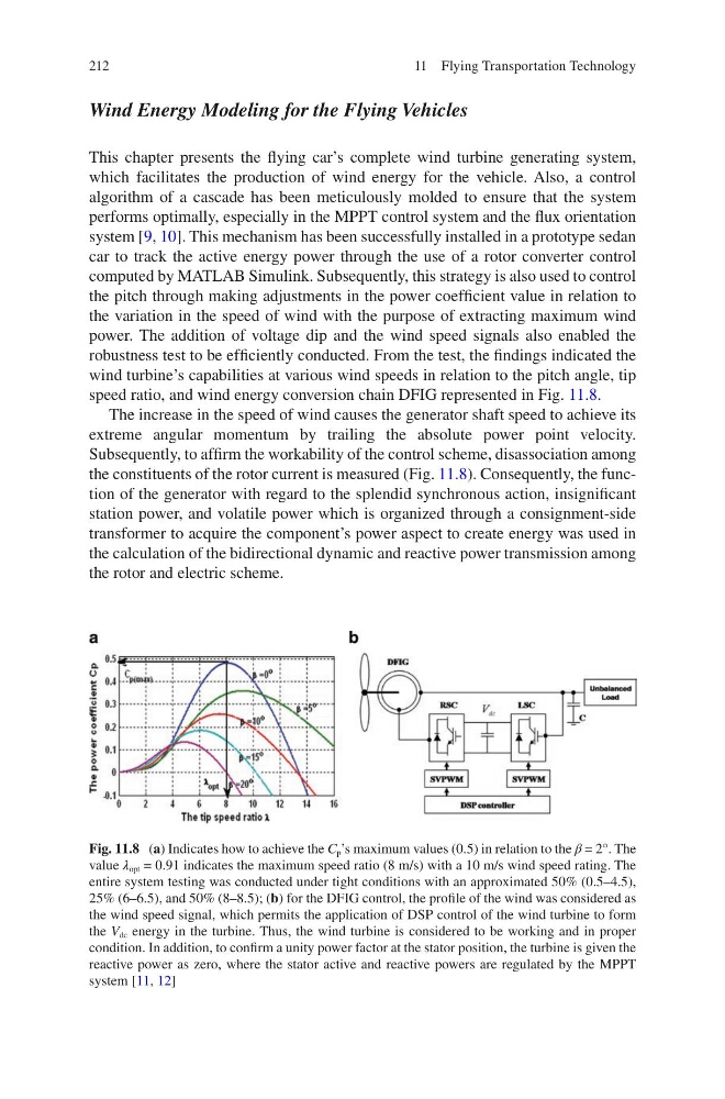
speed ratio, and wind energy conversion chain DFIG represented in Fig. 11.8.
The increase in the speed of wind causes the generator shaft speed to achieve its
extreme angular momentum by trailing the absolute power point velocity.
Subsequently, to affirm the workability of the control scheme, disassociation among
the constituents of the rotor current is measured (Fig. 11.8). Consequently, the function of the generator with regard to the splendid synchronous action, insignificant
station power, and volatile power which is organized through a consignment-side
transformer to acquire the component’s power aspect to create energy was used in
the calculation of the bidirectional dynamic and reactive power transmission among
the rotor and electric scheme.
Fig. 11.8 (a) Indicates how to achieve the C p ’s maximum values (0.5) in relation to the β = 2°. The
value λ opt = 0.91 indicates the maximum speed ratio (8 m/s) with a 10 m/s wind speed rating. The
entire system testing was conducted under tight conditions with an approximated 50% (0.5–4.5),
25% (6–6.5), and 50% (8–8.5); (b) for the DFIG control, the profile of the wind was considered as
the wind speed signal, which permits the application of DSP control of the wind turbine to form
the V dc energy in the turbine. Thus, the wind turbine is considered to be working and in proper
condition. In addition, to confirm a unity power factor at the stator position, the turbine is given the
reactive power as zero, where the stator active and reactive powers are regulated by the MPPT
system [11, 12]
11 Flying Transportation Technology
Wind Energy Modeling for the Flying Vehicles
This chapter presents the flying car’s complete wind turbine generating system,
which facilitates the production of wind energy for the vehicle. Also, a control
algorithm of a cascade has been meticulously molded to ensure that the system
performs optimally, especially in the MPPT control system and the flux orientation
system [9, 10]. This mechanism has been successfully installed in a prototype sedan
car to track the active energy power through the use of a rotor converter control
computed by MATLAB Simulink. Subsequently, this strategy is also used to control
the pitch through making adjustments in the power coefficient value in relation to
the variation in the speed of wind with the purpose of extracting maximum wind
power. The addition of voltage dip and the wind speed signals also enabled the
robustness test to be efficiently conducted. From the test, the findings indicated the
wind turbine’s capabilities at various wind speeds in relation to the pitch angle, tip
speed ratio, and wind energy conversion chain DFIG represented in Fig. 11.8.
The increase in the speed of wind causes the generator shaft speed to achieve its
extreme angular momentum by trailing the absolute power point velocity.
Subsequently, to affirm the workability of the control scheme, disassociation among
the constituents of the rotor current is measured (Fig. 11.8). Consequently, the function of the generator with regard to the splendid synchronous action, insignificant
station power, and volatile power which is organized through a consignment-side
transformer to acquire the component’s power aspect to create energy was used in
the calculation of the bidirectional dynamic and reactive power transmission among
the rotor and electric scheme.
Fig. 11.8 (a) Indicates how to achieve the C p ’s maximum values (0.5) in relation to the β = 2°. The
value λ opt = 0.91 indicates the maximum speed ratio (8 m/s) with a 10 m/s wind speed rating. The
entire system testing was conducted under tight conditions with an approximated 50% (0.5–4.5),
25% (6–6.5), and 50% (8–8.5); (b) for the DFIG control, the profile of the wind was considered as
the wind speed signal, which permits the application of DSP control of the wind turbine to form
the V dc energy in the turbine. Thus, the wind turbine is considered to be working and in proper
condition. In addition, to confirm a unity power factor at the stator position, the turbine is given the
reactive power as zero, where the stator active and reactive powers are regulated by the MPPT
system [11, 12]
11 Flying Transportation Technology