

210
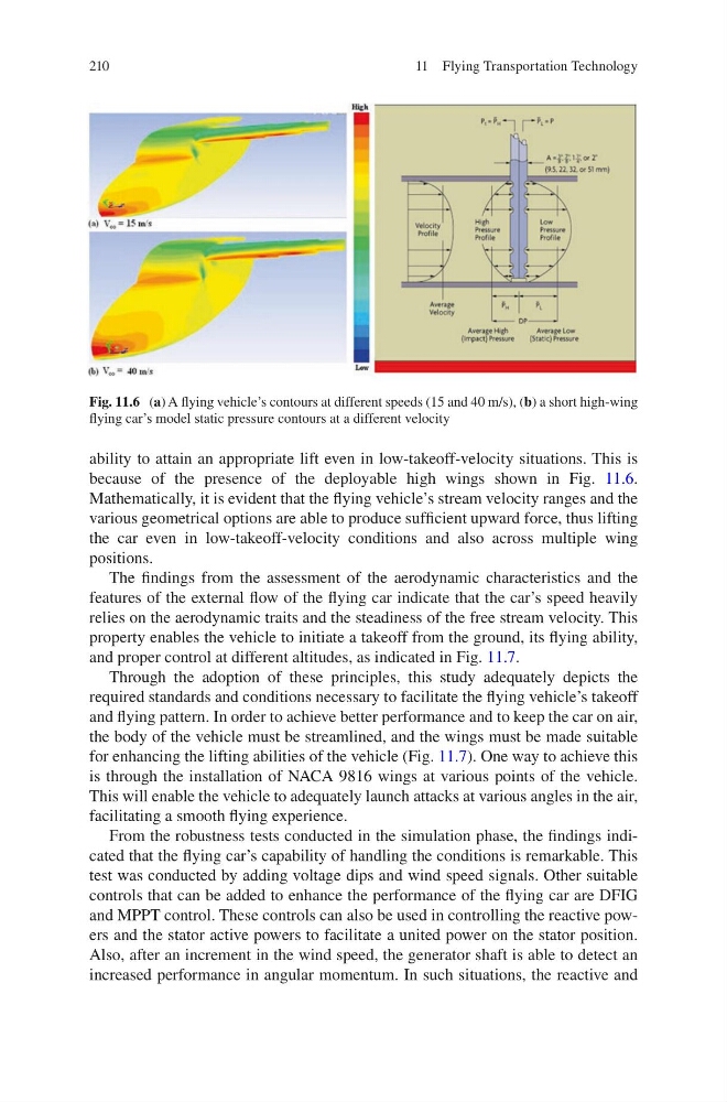
ability to attain an appropriate lift even in low-takeoff-velocity situations. This is
because of the presence of the deployable high wings shown in Fig. 11.6.
Mathematically, it is evident that the flying vehicle’s stream velocity ranges and the
various geometrical options are able to produce sufficient upward force, thus lifting
the car even in low-takeoff-velocity conditions and also across multiple wing
positions.
The findings from the assessment of the aerodynamic characteristics and the
features of the external flow of the flying car indicate that the car’s speed heavily
relies on the aerodynamic traits and the steadiness of the free stream velocity. This
property enables the vehicle to initiate a takeoff from the ground, its flying ability,
and proper control at different altitudes, as indicated in Fig. 11.7.
Through the adoption of these principles, this study adequately depicts the
required standards and conditions necessary to facilitate the flying vehicle’s takeoff
and flying pattern. In order to achieve better performance and to keep the car on air,
the body of the vehicle must be streamlined, and the wings must be made suitable
for enhancing the lifting abilities of the vehicle (Fig. 11.7). One way to achieve this
is through the installation of NACA 9816 wings at various points of the vehicle.
This will enable the vehicle to adequately launch attacks at various angles in the air,
facilitating a smooth flying experience.
From the robustness tests conducted in the simulation phase, the findings indicated that the flying car’s capability of handling the conditions is remarkable. This
test was conducted by adding voltage dips and wind speed signals. Other suitable
controls that can be added to enhance the performance of the flying car are DFIG
and MPPT control. These controls can also be used in controlling the reactive powers and the stator active powers to facilitate a united power on the stator position.
Also, after an increment in the wind speed, the generator shaft is able to detect an
increased performance in angular momentum. In such situations, the reactive and
Fig. 11.6 (a) A flying vehicle’s contours at different speeds (15 and 40 m/s), (b) a short high-wing
flying car’s model static pressure contours at a different velocity
11 Flying Transportation Technology
ability to attain an appropriate lift even in low-takeoff-velocity situations. This is
because of the presence of the deployable high wings shown in Fig. 11.6.
Mathematically, it is evident that the flying vehicle’s stream velocity ranges and the
various geometrical options are able to produce sufficient upward force, thus lifting
the car even in low-takeoff-velocity conditions and also across multiple wing
positions.
The findings from the assessment of the aerodynamic characteristics and the
features of the external flow of the flying car indicate that the car’s speed heavily
relies on the aerodynamic traits and the steadiness of the free stream velocity. This
property enables the vehicle to initiate a takeoff from the ground, its flying ability,
and proper control at different altitudes, as indicated in Fig. 11.7.
Through the adoption of these principles, this study adequately depicts the
required standards and conditions necessary to facilitate the flying vehicle’s takeoff
and flying pattern. In order to achieve better performance and to keep the car on air,
the body of the vehicle must be streamlined, and the wings must be made suitable
for enhancing the lifting abilities of the vehicle (Fig. 11.7). One way to achieve this
is through the installation of NACA 9816 wings at various points of the vehicle.
This will enable the vehicle to adequately launch attacks at various angles in the air,
facilitating a smooth flying experience.
From the robustness tests conducted in the simulation phase, the findings indicated that the flying car’s capability of handling the conditions is remarkable. This
test was conducted by adding voltage dips and wind speed signals. Other suitable
controls that can be added to enhance the performance of the flying car are DFIG
and MPPT control. These controls can also be used in controlling the reactive powers and the stator active powers to facilitate a united power on the stator position.
Also, after an increment in the wind speed, the generator shaft is able to detect an
increased performance in angular momentum. In such situations, the reactive and
Fig. 11.6 (a) A flying vehicle’s contours at different speeds (15 and 40 m/s), (b) a short high-wing
flying car’s model static pressure contours at a different velocity
11 Flying Transportation Technology