

186
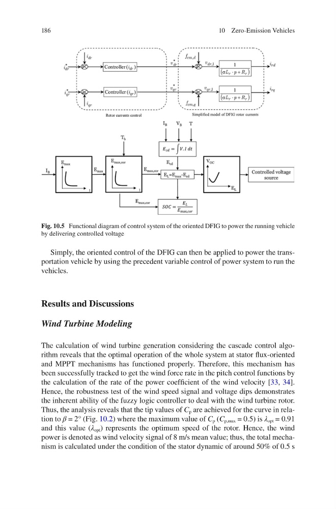
Simply, the oriented control of the DFIG can then be applied to power the transportation vehicle by using the precedent variable control of power system to run the
vehicles.
Results and Discussions
Wind Turbine Modeling
The calculation of wind turbine generation considering the cascade control algorithm reveals that the optimal operation of the whole system at stator flux-oriented
and MPPT mechanisms has functioned properly. Therefore, this mechanism has
been successfully tracked to get the wind force rate in the pitch control functions by
the calculation of the rate of the power coefficient of the wind velocity [33, 34].
Hence, the robustness test of the wind speed signal and voltage dips demonstrates
the inherent ability of the fuzzy logic controller to deal with the wind turbine rotor.
Thus, the analysis reveals that the tip values of C p are achieved for the curve in relation to β = 2° (Fig. 10.2) where the maximum value of C p (C p,max = 0.5) is λ opt = 0.91
and this value (λ opt ) represents the optimum speed of the rotor. Hence, the wind
power is denoted as wind velocity signal of 8 m/s mean value; thus, the total mechanism is calculated under the condition of the stator dynamic of around 50% of 0.5 s
Fig. 10.5 Functional diagram of control system of the oriented DFIG to power the running vehicle
by delivering controlled voltage
10 Zero-Emission Vehicles
Simply, the oriented control of the DFIG can then be applied to power the transportation vehicle by using the precedent variable control of power system to run the
vehicles.
Results and Discussions
Wind Turbine Modeling
The calculation of wind turbine generation considering the cascade control algorithm reveals that the optimal operation of the whole system at stator flux-oriented
and MPPT mechanisms has functioned properly. Therefore, this mechanism has
been successfully tracked to get the wind force rate in the pitch control functions by
the calculation of the rate of the power coefficient of the wind velocity [33, 34].
Hence, the robustness test of the wind speed signal and voltage dips demonstrates
the inherent ability of the fuzzy logic controller to deal with the wind turbine rotor.
Thus, the analysis reveals that the tip values of C p are achieved for the curve in relation to β = 2° (Fig. 10.2) where the maximum value of C p (C p,max = 0.5) is λ opt = 0.91
and this value (λ opt ) represents the optimum speed of the rotor. Hence, the wind
power is denoted as wind velocity signal of 8 m/s mean value; thus, the total mechanism is calculated under the condition of the stator dynamic of around 50% of 0.5 s
Fig. 10.5 Functional diagram of control system of the oriented DFIG to power the running vehicle
by delivering controlled voltage
10 Zero-Emission Vehicles