

185
with fem d and fem q being the crossed coupling terms between the d-axis and q-axis:
fem
fem
r r r
r r r
s
s
d
q
q
d
L i
L i
s
M
L
V
= −
=
+
σ ω
σ ω
(10.23)
Further considering Eqs. (10.10) and (10.12), the current fluxes are simplified as
φ d
d
d
q
q
L i
Mi
L i
Mi
s
s s
r
s s
r
=
+
=
+
0
(10.24)
From (10.15), the determination of the deduced currents is expressed as
i
Mi
L
i
M
L
i
d
d
d
q
q
s
s
r
s
s
s
r
=
−
= −
φ
(10.25)
Finally, the stator is linked to these rotor currents precisely as
P
V
M
L
i
Q
V
M
L
i
M
q
d
d
s
s
s
r
s
s
s
r
s
= − ∗
= − ∗
−
φ
(10.26)
where the stator active and reactive powers are controlled by means of i qr and i dr ,
respectively (Fig. 10.5).
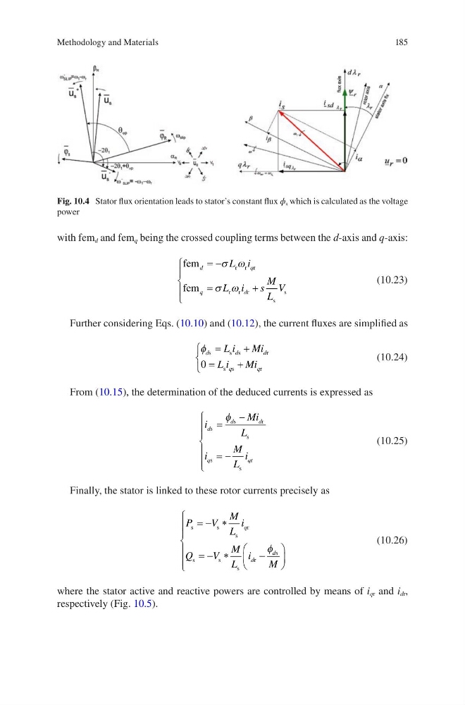
Fig. 10.4 Stator flux orientation leads to stator’s constant flux ϕ s which is calculated as the voltage
power
Methodology and Materials
with fem d and fem q being the crossed coupling terms between the d-axis and q-axis:
fem
fem
r r r
r r r
s
s
d
q
q
d
L i
L i
s
M
L
V
= −
=
+
σ ω
σ ω
(10.23)
Further considering Eqs. (10.10) and (10.12), the current fluxes are simplified as
φ d
d
d
q
q
L i
Mi
L i
Mi
s
s s
r
s s
r
=
+
=
+
0
(10.24)
From (10.15), the determination of the deduced currents is expressed as
i
Mi
L
i
M
L
i
d
d
d
q
q
s
s
r
s
s
s
r
=
−
= −
φ
(10.25)
Finally, the stator is linked to these rotor currents precisely as
P
V
M
L
i
Q
V
M
L
i
M
q
d
d
s
s
s
r
s
s
s
r
s
= − ∗
= − ∗
−
φ
(10.26)
where the stator active and reactive powers are controlled by means of i qr and i dr ,
respectively (Fig. 10.5).
Fig. 10.4 Stator flux orientation leads to stator’s constant flux ϕ s which is calculated as the voltage
power
Methodology and Materials