

184
Since the DFIG is interconnected to the power rotor of the transportation vehicle,
the stator flux vector at the d-axis directional has been calculated and expressed as
the following equation (Fig. 10.4):
φ φ
φ
s
s
s
=
⇒
=
d
q
0
(10.19)
Conducting the above equation, the vehicle power system, the functional voltage
V s , and the stator’s constant flux ϕ s are calculated as
v
v
V
d
q
s
s
s
s
s
=
= ∗ =
0
ω φ
(10.20)
Hence, the stator voltage vectors are in the direction of quadrate advances which
is further clarified by using Eqs. (10.11) and (10.5) to obtain voltages for rotor:
v
L
di
dt
R i
L i
M
L
d
dt
v
L
di
dt
R i
d
d
d
q
d
q
q
q
r
r
r
r r
r r r
s
s
r
r
r
r r
=
+
−
+
=
+
+
σ
σ ω
φ
σ
σ σ ω
L i
g
M
L
V
d
r r r
s
s
+
(10.21)
where V s represents the stator voltage and g represents the slip range and thus it can
be rewritten as follows:
v
L
di
dt
R i
v
L
di
dt
R i
d
d
d
d
q
q
q
q
r
r
r
r r
r
r
r
r r
fem
fem
=
+
+
=
+
+
σ
σ
(10.22)
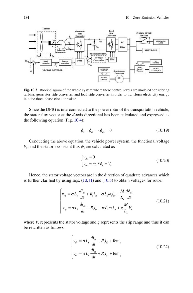
Fig. 10.3 Block diagram of the whole system where these control levels are modeled considering
turbine, generator-side converter, and load-side converter in order to transform electricity energy
into the three-phase circuit breaker
10 Zero-Emission Vehicles
Since the DFIG is interconnected to the power rotor of the transportation vehicle,
the stator flux vector at the d-axis directional has been calculated and expressed as
the following equation (Fig. 10.4):
φ φ
φ
s
s
s
=
⇒
=
d
q
0
(10.19)
Conducting the above equation, the vehicle power system, the functional voltage
V s , and the stator’s constant flux ϕ s are calculated as
v
v
V
d
q
s
s
s
s
s
=
= ∗ =
0
ω φ
(10.20)
Hence, the stator voltage vectors are in the direction of quadrate advances which
is further clarified by using Eqs. (10.11) and (10.5) to obtain voltages for rotor:
v
L
di
dt
R i
L i
M
L
d
dt
v
L
di
dt
R i
d
d
d
q
d
q
q
q
r
r
r
r r
r r r
s
s
r
r
r
r r
=
+
−
+
=
+
+
σ
σ ω
φ
σ
σ σ ω
L i
g
M
L
V
d
r r r
s
s
+
(10.21)
where V s represents the stator voltage and g represents the slip range and thus it can
be rewritten as follows:
v
L
di
dt
R i
v
L
di
dt
R i
d
d
d
d
q
q
q
q
r
r
r
r r
r
r
r
r r
fem
fem
=
+
+
=
+
+
σ
σ
(10.22)
Fig. 10.3 Block diagram of the whole system where these control levels are modeled considering
turbine, generator-side converter, and load-side converter in order to transform electricity energy
into the three-phase circuit breaker
10 Zero-Emission Vehicles