

183
V
d
dt
R
L
M
R
L
i
V
d
dt
R
L
d
d
d
q
q
q
q
d
q
s
s
s
s
s
s
s
s
s
r
s
s
s
s
s
s
=
+
− ∗ −
=
+ ∗ +
φ
φ ω φ
φ
ω φ
φ s s
s
s
r
r
s
s
r
r
s
s
s
s
s
r
−
−
=
−
+
+
M
R
L
i V
M
L
V
L
di
dt
M
R
L
M
L
R
q
d
d
d
d
q
σ
φ
ωφ
2
+ +
−
−
=
−
M
L R
i
L i
v
M
L
v
L
di
dt
M
L
d
q
q
d
q
2
2
s s
r
r r r
r
s
s
r
r
s
σ ω
σ
ω φ φ
φ σ ω
d
q
d
d
M
R
L
L i
R
M
L R
i
s
s
s
s
r r r
r
s s
r
−
+
+
+
2
2
2
(10.15)
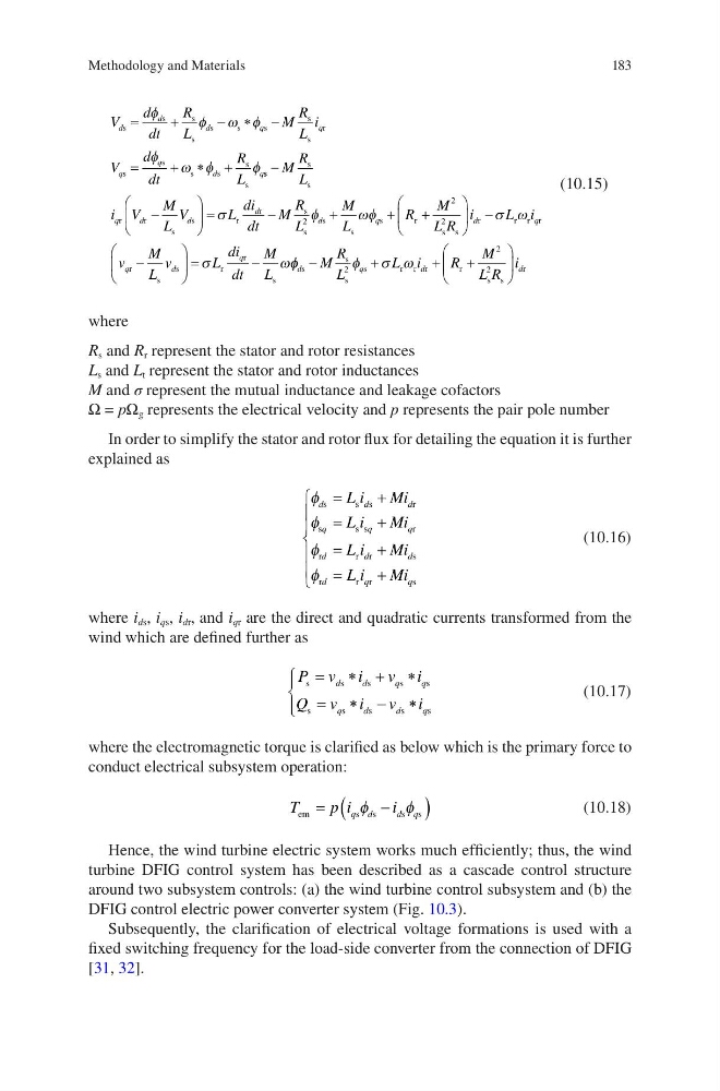
where
R s and R r represent the stator and rotor resistances
L s and L t represent the stator and rotor inductances
M and σ represent the mutual inductance and leakage cofactors
Ω = pΩ g represents the electrical velocity and p represents the pair pole number
In order to simplify the stator and rotor flux for detailing the equation it is further
explained as
φ
φ
φ
φ
d
d
d
q
q
q
d
d
d
d
q
q
L i
Mi
L i
Mi
L i
Mi
L i
Mi
s
s s
r
s
ss
r
r
r r
s
r
r r
s
=
+
=
+
=
+
=
+
(10.16)
where i ds , i qs , i dr , and i qr are the direct and quadratic currents transformed from the
wind which are defined further as
P v i
v i
Q v i
v i
d
d
q
q
q
d
d
q
s
s
s
s
s
s
s
s
s
s
= ∗ + ∗
= ∗ − ∗
(10.17)
where the electromagnetic torque is clarified as below which is the primary force to
conduct electrical subsystem operation:
T
p i
i
q d
d q
em
s s
s s
=
−
(
)
φ
φ
(10.18)
Hence, the wind turbine electric system works much efficiently; thus, the wind
turbine DFIG control system has been described as a cascade control structure
around two subsystem controls: (a) the wind turbine control subsystem and (b) the
DFIG control electric power converter system (Fig. 10.3).
Subsequently, the clarification of electrical voltage formations is used with a
fixed switching frequency for the load-side converter from the connection of DFIG
[31, 32].
Methodology and Materials
V
d
dt
R
L
M
R
L
i
V
d
dt
R
L
d
d
d
q
q
q
q
d
q
s
s
s
s
s
s
s
s
s
r
s
s
s
s
s
s
=
+
− ∗ −
=
+ ∗ +
φ
φ ω φ
φ
ω φ
φ s s
s
s
r
r
s
s
r
r
s
s
s
s
s
r
−
−
=
−
+
+
M
R
L
i V
M
L
V
L
di
dt
M
R
L
M
L
R
q
d
d
d
d
q
σ
φ
ωφ
2
+ +
−
−
=
−
M
L R
i
L i
v
M
L
v
L
di
dt
M
L
d
q
q
d
q
2
2
s s
r
r r r
r
s
s
r
r
s
σ ω
σ
ω φ φ
φ σ ω
d
q
d
d
M
R
L
L i
R
M
L R
i
s
s
s
s
r r r
r
s s
r
−
+
+
+
2
2
2
(10.15)
where
R s and R r represent the stator and rotor resistances
L s and L t represent the stator and rotor inductances
M and σ represent the mutual inductance and leakage cofactors
Ω = pΩ g represents the electrical velocity and p represents the pair pole number
In order to simplify the stator and rotor flux for detailing the equation it is further
explained as
φ
φ
φ
φ
d
d
d
q
q
q
d
d
d
d
q
q
L i
Mi
L i
Mi
L i
Mi
L i
Mi
s
s s
r
s
ss
r
r
r r
s
r
r r
s
=
+
=
+
=
+
=
+
(10.16)
where i ds , i qs , i dr , and i qr are the direct and quadratic currents transformed from the
wind which are defined further as
P v i
v i
Q v i
v i
d
d
q
q
q
d
d
q
s
s
s
s
s
s
s
s
s
s
= ∗ + ∗
= ∗ − ∗
(10.17)
where the electromagnetic torque is clarified as below which is the primary force to
conduct electrical subsystem operation:
T
p i
i
q d
d q
em
s s
s s
=
−
(
)
φ
φ
(10.18)
Hence, the wind turbine electric system works much efficiently; thus, the wind
turbine DFIG control system has been described as a cascade control structure
around two subsystem controls: (a) the wind turbine control subsystem and (b) the
DFIG control electric power converter system (Fig. 10.3).
Subsequently, the clarification of electrical voltage formations is used with a
fixed switching frequency for the load-side converter from the connection of DFIG
[31, 32].
Methodology and Materials