

182
where ρ represents the air density, R represents the blade length, and V represents
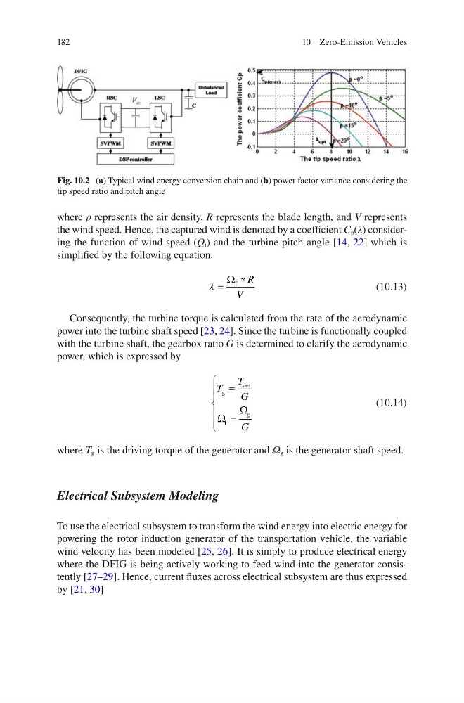
the wind speed. Hence, the captured wind is denoted by a coefficient C p (λ) considering the function of wind speed (Q t ) and the turbine pitch angle [14, 22] which is
simplified by the following equation:
λ =
∗
Ω T R
V
(10.13)
Consequently, the turbine torque is calculated from the rate of the aerodynamic
power into the turbine shaft speed [23, 24]. Since the turbine is functionally coupled
with the turbine shaft, the gearbox ratio G is determined to clarify the aerodynamic
power, which is expressed by
T
T
G
G
g
aer
t
g
=
=
Ω
Ω
(10.14)
where T g is the driving torque of the generator and Ω g is the generator shaft speed.
Electrical Subsystem Modeling
To use the electrical subsystem to transform the wind energy into electric energy for
powering the rotor induction generator of the transportation vehicle, the variable
wind velocity has been modeled [25, 26]. It is simply to produce electrical energy
where the DFIG is being actively working to feed wind into the generator consistently [27–29]. Hence, current fluxes across electrical subsystem are thus expressed
by [21, 30]
Fig. 10.2 (a) Typical wind energy conversion chain and (b) power factor variance considering the
tip speed ratio and pitch angle
10 Zero-Emission Vehicles
where ρ represents the air density, R represents the blade length, and V represents
the wind speed. Hence, the captured wind is denoted by a coefficient C p (λ) considering the function of wind speed (Q t ) and the turbine pitch angle [14, 22] which is
simplified by the following equation:
λ =
∗
Ω T R
V
(10.13)
Consequently, the turbine torque is calculated from the rate of the aerodynamic
power into the turbine shaft speed [23, 24]. Since the turbine is functionally coupled
with the turbine shaft, the gearbox ratio G is determined to clarify the aerodynamic
power, which is expressed by
T
T
G
G
g
aer
t
g
=
=
Ω
Ω
(10.14)
where T g is the driving torque of the generator and Ω g is the generator shaft speed.
Electrical Subsystem Modeling
To use the electrical subsystem to transform the wind energy into electric energy for
powering the rotor induction generator of the transportation vehicle, the variable
wind velocity has been modeled [25, 26]. It is simply to produce electrical energy
where the DFIG is being actively working to feed wind into the generator consistently [27–29]. Hence, current fluxes across electrical subsystem are thus expressed
by [21, 30]
Fig. 10.2 (a) Typical wind energy conversion chain and (b) power factor variance considering the
tip speed ratio and pitch angle
10 Zero-Emission Vehicles