

166
adjusted by altering the timing of the polarity shift in the propulsion coils’ magnetic
field between north and south with the possibility of maximum speed of 580 kph [20,
21]. As the vehicle passes just 2 ft above the guideway (1 ft from the earth surface),
an electric current is induced in the levitation and guidance coils, creating opposite
magnetic poles in the upper and lower loops. The upper loops become the polar
opposite of the vehicle’s magnets, producing attraction, which pulls the vehicle up.
The lower loops have the same pole as the magnets. This generates repulsion, which
pushes the vehicle in the same direction up. The two forces combine to levitate the
vehicle while maintaining its lateral balance between the walls of the guideway.
Subsequently a niobium-titanium alloy is to be used to create superconducting
magnets for maglev, but to reach superconductivity, they must be kept cold. In order
to keep the alloy cool, liquid helium should be used at a temperature of −269 °C
since alloy retains superconductivity at temperatures up to −263 °C, though the
maglev system can operate better at 6 °C to produce sufficient magnetic force.
In addition to underground maglev, the wind turbine generation system for the
backup energy source is to be implemented for the optimal operation of the whole
system and a robustness test should be performed by adding a wind speed signal and
power coefficient.
Fig. 9.6 The maglev vehicle’s force and directional diagram as shown by propulsion guidance
coils and superconducting coils
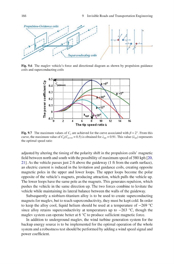
Fig. 9.7 The maximum values of C p are achieved for the curve associated with β = 2°. From this
curve, the maximum value of C p (C p,max = 0.5) is obtained for λ opt = 0.91. This value (λ opt ) represents
the optimal speed ratio
9 Invisible Roads and Transportation Engineering
adjusted by altering the timing of the polarity shift in the propulsion coils’ magnetic
field between north and south with the possibility of maximum speed of 580 kph [20,
21]. As the vehicle passes just 2 ft above the guideway (1 ft from the earth surface),
an electric current is induced in the levitation and guidance coils, creating opposite
magnetic poles in the upper and lower loops. The upper loops become the polar
opposite of the vehicle’s magnets, producing attraction, which pulls the vehicle up.
The lower loops have the same pole as the magnets. This generates repulsion, which
pushes the vehicle in the same direction up. The two forces combine to levitate the
vehicle while maintaining its lateral balance between the walls of the guideway.
Subsequently a niobium-titanium alloy is to be used to create superconducting
magnets for maglev, but to reach superconductivity, they must be kept cold. In order
to keep the alloy cool, liquid helium should be used at a temperature of −269 °C
since alloy retains superconductivity at temperatures up to −263 °C, though the
maglev system can operate better at 6 °C to produce sufficient magnetic force.
In addition to underground maglev, the wind turbine generation system for the
backup energy source is to be implemented for the optimal operation of the whole
system and a robustness test should be performed by adding a wind speed signal and
power coefficient.
Fig. 9.6 The maglev vehicle’s force and directional diagram as shown by propulsion guidance
coils and superconducting coils
Fig. 9.7 The maximum values of C p are achieved for the curve associated with β = 2°. From this
curve, the maximum value of C p (C p,max = 0.5) is obtained for λ opt = 0.91. This value (λ opt ) represents
the optimal speed ratio
9 Invisible Roads and Transportation Engineering