

167
These conditions permit application of the wind profile considered to be a wind
speed signal with a mean value of 8 m/s and a rated wind speed of 10 m/s; the whole
system is tested under standard conditions with a stator voltage of approximately
50% for 0.5 s between 4 and 4.5 s, approximately 25% between 6 and 6.5 s, and
50% between 8 and 8.5 s (Fig. 9.7). Thus, the machine is considered to be functioning in ideal conditions (no perturbations and no parameter variations). Moreover, to
guarantee a unity power factor at the stator side, the reference for the reactive power
has to be set to zero [22]. As a result of increasing wind speed, the generator shaft
speed achieves maximum angular speed by tracking the maximum power point
speed. Thus, the wind turbine always works optimally since the pole placement
technique is to be used to design the tracking control [23]. Consequently, decoupling among the components of the rotor current was also performed to confirm that
the control system worked effectively. The bidirectional active and reactive power
transfer between the rotor and power system is exchanged by the generator according to the supersynchronous operation, achieving the nominal stator power, and the
reactive power can be controlled by the load-side converter to obtain the unit’s
power factor to generate energy for powering vehicles [24, 25].
Construction Cost Estimate Comparison
Order of magnitude cost estimate was performed by using HCSS (Heavy Bid) software standard union rate of New York State locals with a project of 10% general
condition, 10% overhead and profit, and 3% contingency over the hard cost of labor,
materials, and equipment comparing between maglev infrastructure and traditional
infrastructure system for a sample of 100 miles long and 128 ft wide (12 ft wide of
4 lanes in each direction, two-sided 10 ft service space, and 6 ft median in the center
of the road). In order to determine that the underground guideway (w24 × 84) can
last long I have calculated again the LRFD to provide the shoring to both sides for
the entire 100 miles long and 128 ft wide (12 ft wide of 4 lanes in each direction,
two-sided 10 ft service space, and 6 ft median in the center of the road) construction
cost considering standard excavation up to 6 ft deep, with appropriate shoring with
minimum embedment depth L 4 being 5 ft, standard soil pressure ϒ s = 120 lbf/ft
3
,
angle of pressure Φ = 21°, and soil pressure coefficient c = 800 lbf/ft
2
. To prepare
the conceptual estimate we need to determine the length of soldier piles. I have
counted 6′ OC (on center) soldier piles on both sides by illustration and using the
following LRFD method the soldier piles must be set to support the necessary excavation and/or earth pressure against collapse:
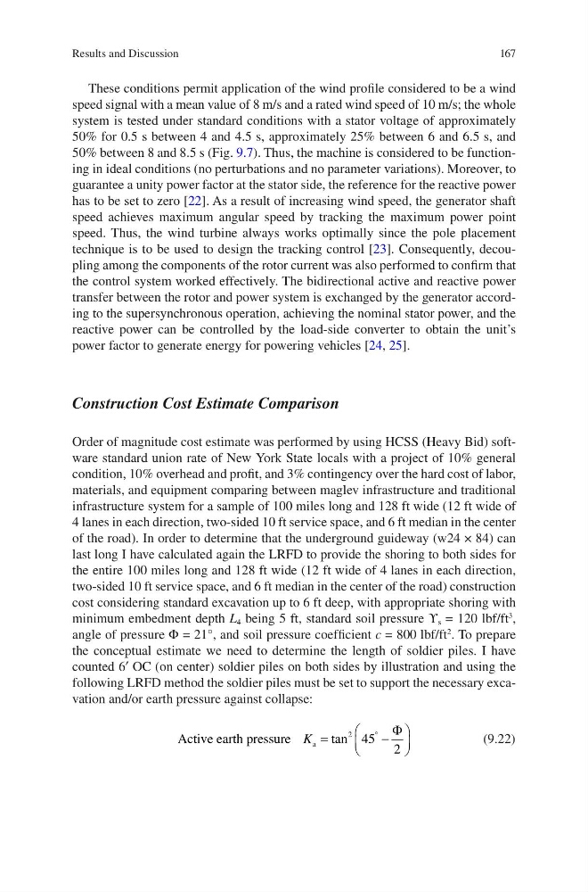
Active earth pressure
a
K
§
©
¨
·
¹
¸
q
tan
2 45 2
)
(9.22)
Results and Discussion
These conditions permit application of the wind profile considered to be a wind
speed signal with a mean value of 8 m/s and a rated wind speed of 10 m/s; the whole
system is tested under standard conditions with a stator voltage of approximately
50% for 0.5 s between 4 and 4.5 s, approximately 25% between 6 and 6.5 s, and
50% between 8 and 8.5 s (Fig. 9.7). Thus, the machine is considered to be functioning in ideal conditions (no perturbations and no parameter variations). Moreover, to
guarantee a unity power factor at the stator side, the reference for the reactive power
has to be set to zero [22]. As a result of increasing wind speed, the generator shaft
speed achieves maximum angular speed by tracking the maximum power point
speed. Thus, the wind turbine always works optimally since the pole placement
technique is to be used to design the tracking control [23]. Consequently, decoupling among the components of the rotor current was also performed to confirm that
the control system worked effectively. The bidirectional active and reactive power
transfer between the rotor and power system is exchanged by the generator according to the supersynchronous operation, achieving the nominal stator power, and the
reactive power can be controlled by the load-side converter to obtain the unit’s
power factor to generate energy for powering vehicles [24, 25].
Construction Cost Estimate Comparison
Order of magnitude cost estimate was performed by using HCSS (Heavy Bid) software standard union rate of New York State locals with a project of 10% general
condition, 10% overhead and profit, and 3% contingency over the hard cost of labor,
materials, and equipment comparing between maglev infrastructure and traditional
infrastructure system for a sample of 100 miles long and 128 ft wide (12 ft wide of
4 lanes in each direction, two-sided 10 ft service space, and 6 ft median in the center
of the road). In order to determine that the underground guideway (w24 × 84) can
last long I have calculated again the LRFD to provide the shoring to both sides for
the entire 100 miles long and 128 ft wide (12 ft wide of 4 lanes in each direction,
two-sided 10 ft service space, and 6 ft median in the center of the road) construction
cost considering standard excavation up to 6 ft deep, with appropriate shoring with
minimum embedment depth L 4 being 5 ft, standard soil pressure ϒ s = 120 lbf/ft
3
,
angle of pressure Φ = 21°, and soil pressure coefficient c = 800 lbf/ft
2
. To prepare
the conceptual estimate we need to determine the length of soldier piles. I have
counted 6′ OC (on center) soldier piles on both sides by illustration and using the
following LRFD method the soldier piles must be set to support the necessary excavation and/or earth pressure against collapse:
Active earth pressure
a
K
§
©
¨
·
¹
¸
q
tan
2 45 2
)
(9.22)
Results and Discussion