

165
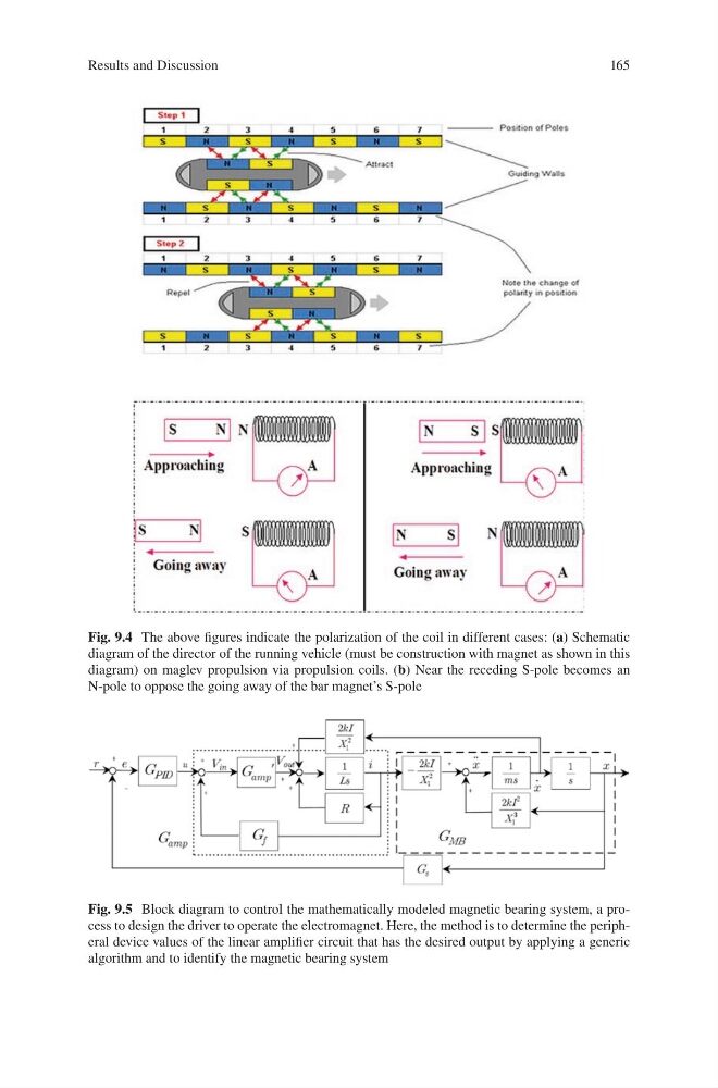
Fig. 9.4 The above figures indicate the polarization of the coil in different cases: (a) Schematic
diagram of the director of the running vehicle (must be construction with magnet as shown in this
diagram) on maglev propulsion via propulsion coils. (b) Near the receding S-pole becomes an
N-pole to oppose the going away of the bar magnet’s S-pole
Fig. 9.5 Block diagram to control the mathematically modeled magnetic bearing system, a process to design the driver to operate the electromagnet. Here, the method is to determine the peripheral device values of the linear amplifier circuit that has the desired output by applying a generic
algorithm and to identify the magnetic bearing system
Results and Discussion
Fig. 9.4 The above figures indicate the polarization of the coil in different cases: (a) Schematic
diagram of the director of the running vehicle (must be construction with magnet as shown in this
diagram) on maglev propulsion via propulsion coils. (b) Near the receding S-pole becomes an
N-pole to oppose the going away of the bar magnet’s S-pole
Fig. 9.5 Block diagram to control the mathematically modeled magnetic bearing system, a process to design the driver to operate the electromagnet. Here, the method is to determine the peripheral device values of the linear amplifier circuit that has the desired output by applying a generic
algorithm and to identify the magnetic bearing system
Results and Discussion