

164
Results and Discussion
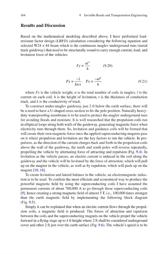
Based on the mathematical modeling described above, I have performed loadresistant factor design (LRFD) calculation considering the following equation and
selected W24 × 84 beam which is the continuous maglev underground runs (metal
track guideway) that need to be structurally sound to carry enough current, load, and
levitation force of the vehicles:
Fy
nl
h
∝
2
(9.20)
Fx ktvx
Fx
nl
h
v
v
1
2
(9.21)
where Fy is the vehicle weight, n is the total number of coils in maglev, l is the
current on each coil, h is the height of levitation, t is the thickness of conduction
track, and k is the conductivity of track.
To construct under-maglev guideway just 2 ft below the earth surface, there will
be a need to have a U-shaped cross section to fix the pole position. Naturally heavyduty waterproofing membrane is to be used to protect the maglev underground runs
for avoiding floods and moisture. It is well researched that the propulsion coils run
in elliptical loops along both walls of the guideway, generating magnetic force when
electricity runs through them. So, levitation and guidance coils will be formed that
will create their own magnetic force once the applied superconducting magnets pass
on it where propulsion and levitation are the key factors to run the vehicle. In propulsion, as the direction of the current charges back and forth in the propulsion coils
above the wall of the guideway, the north and south poles will reverse repeatedly,
propelling the vehicle by alternating force of attracting and repulsion (Fig. 9.4). In
levitation as the vehicle passes, an electric current is induced in the coil along the
guideway and the vehicle will be levitated by the force of attraction, which will pull
up on the magnet in the vehicle, as well as by repulsion, which will push up on the
magnet [10, 18].
To create levitation and lateral balance in the vehicle, an electromagnetic induction is to be used. To confirm the most efficient and economical way to produce the
powerful magnetic field by using the superconducting coils I have assumed the
permanent currents of about 700,000 A to go through these superconducting coils
[9], hence creating a strong magnetic field of almost 5 T, i.e., 100,000 times stronger
than the earth magnetic field by implementing the following block diagram
(Fig. 9.5).
Simply it can be explained that when an electric current flows through the propulsion coils, a magnetic field is produced. The forces of attraction and repulsion
between the coils and the superconducting magnets on the vehicle propel the vehicle
forward in a flying stage up to 4 ft height where 2 ft shall be considered underground
cover and other 2 ft just over the earth surface (Fig. 9.6). The vehicle’s speed is to be
9 Invisible Roads and Transportation Engineering
Results and Discussion
Based on the mathematical modeling described above, I have performed loadresistant factor design (LRFD) calculation considering the following equation and
selected W24 × 84 beam which is the continuous maglev underground runs (metal
track guideway) that need to be structurally sound to carry enough current, load, and
levitation force of the vehicles:
Fy
nl
h
∝
2
(9.20)
Fx ktvx
Fx
nl
h
v
v
1
2
(9.21)
where Fy is the vehicle weight, n is the total number of coils in maglev, l is the
current on each coil, h is the height of levitation, t is the thickness of conduction
track, and k is the conductivity of track.
To construct under-maglev guideway just 2 ft below the earth surface, there will
be a need to have a U-shaped cross section to fix the pole position. Naturally heavyduty waterproofing membrane is to be used to protect the maglev underground runs
for avoiding floods and moisture. It is well researched that the propulsion coils run
in elliptical loops along both walls of the guideway, generating magnetic force when
electricity runs through them. So, levitation and guidance coils will be formed that
will create their own magnetic force once the applied superconducting magnets pass
on it where propulsion and levitation are the key factors to run the vehicle. In propulsion, as the direction of the current charges back and forth in the propulsion coils
above the wall of the guideway, the north and south poles will reverse repeatedly,
propelling the vehicle by alternating force of attracting and repulsion (Fig. 9.4). In
levitation as the vehicle passes, an electric current is induced in the coil along the
guideway and the vehicle will be levitated by the force of attraction, which will pull
up on the magnet in the vehicle, as well as by repulsion, which will push up on the
magnet [10, 18].
To create levitation and lateral balance in the vehicle, an electromagnetic induction is to be used. To confirm the most efficient and economical way to produce the
powerful magnetic field by using the superconducting coils I have assumed the
permanent currents of about 700,000 A to go through these superconducting coils
[9], hence creating a strong magnetic field of almost 5 T, i.e., 100,000 times stronger
than the earth magnetic field by implementing the following block diagram
(Fig. 9.5).
Simply it can be explained that when an electric current flows through the propulsion coils, a magnetic field is produced. The forces of attraction and repulsion
between the coils and the superconducting magnets on the vehicle propel the vehicle
forward in a flying stage up to 4 ft height where 2 ft shall be considered underground
cover and other 2 ft just over the earth surface (Fig. 9.6). The vehicle’s speed is to be
9 Invisible Roads and Transportation Engineering