

121
I
T
T
qE T
T
KA
O
R s
C
ref
G
ref
C
I
§
©
¨
·
¹
¸
§
©
¨
·
¹
¸
ª
¬
«
«
«
«
«
º
¼
»
»
»
»
»
3
1
1
exp
(6.41)
where IR s denotes the dynamic current representing the functional transformation of
solar radiation and qE G denotes the bandgap solar radiation in the acting PV cell at
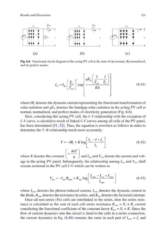
normal, normalized, and perfect modes of electricity generation (Fig. 6.6).
Here, considering this acting PV cell, the I–V relationship with the exception of
I–V curve, a calculative result of linked I–V curves among all cells of the PV panel,
has been determined [51, 52]. Thus, the equation is rewritten as follows in order to
determine the V–R relationship much more accurately:
V
IR K
I I I
I
ª
¬
«
º
¼
»
s
L
o
o
log
(6.42)
where K denotes the constant
§
©
¨
·
¹
¸
AkT
q
and I mo and V mo denote the current and voltage in the acting PV panel. Subsequently, the relationship among I mo and V mo shall
remain motional in the PV cell I–V which can be written as
V
I R
K
I
I
I
I
mo
mo Smo
m o
Lmo
m o
o mo
omo
§
©
¨
·
¹
¸
log
(6.43)
where I Lmo denotes the photon-induced current, I omo denotes the dynamic current in
the diode, R smo denotes the resistance in series, and K mo denotes the factorial constant.
Once all non-series (Ns) cells are interlinked in the series, then the series resistance is calculated as the sum of each cell series resistance R smo = N s × R s current
considering the functional coefficient of the constant factor K mo = N s × K. Since the
flow of current dynamics into the circuit is lined to the cells in a series connection,
the current dynamics in Eq. (6.40) remains the same in each part of I omo = I o and
Fig. 6.6 Functional circuit diagram of the acting PV cell at the state of (a) normal, (b) normalized,
and (c) perfect modes
Results and Discussion
I
T
T
qE T
T
KA
O
R s
C
ref
G
ref
C
I
§
©
¨
·
¹
¸
§
©
¨
·
¹
¸
ª
¬
«
«
«
«
«
º
¼
»
»
»
»
»
3
1
1
exp
(6.41)
where IR s denotes the dynamic current representing the functional transformation of
solar radiation and qE G denotes the bandgap solar radiation in the acting PV cell at
normal, normalized, and perfect modes of electricity generation (Fig. 6.6).
Here, considering this acting PV cell, the I–V relationship with the exception of
I–V curve, a calculative result of linked I–V curves among all cells of the PV panel,
has been determined [51, 52]. Thus, the equation is rewritten as follows in order to
determine the V–R relationship much more accurately:
V
IR K
I I I
I
ª
¬
«
º
¼
»
s
L
o
o
log
(6.42)
where K denotes the constant
§
©
¨
·
¹
¸
AkT
q
and I mo and V mo denote the current and voltage in the acting PV panel. Subsequently, the relationship among I mo and V mo shall
remain motional in the PV cell I–V which can be written as
V
I R
K
I
I
I
I
mo
mo Smo
m o
Lmo
m o
o mo
omo
§
©
¨
·
¹
¸
log
(6.43)
where I Lmo denotes the photon-induced current, I omo denotes the dynamic current in
the diode, R smo denotes the resistance in series, and K mo denotes the factorial constant.
Once all non-series (Ns) cells are interlinked in the series, then the series resistance is calculated as the sum of each cell series resistance R smo = N s × R s current
considering the functional coefficient of the constant factor K mo = N s × K. Since the
flow of current dynamics into the circuit is lined to the cells in a series connection,
the current dynamics in Eq. (6.40) remains the same in each part of I omo = I o and
Fig. 6.6 Functional circuit diagram of the acting PV cell at the state of (a) normal, (b) normalized,
and (c) perfect modes
Results and Discussion