

110
cell current motion (A), and V denotes the cell voltage motion (V). Therefore, the
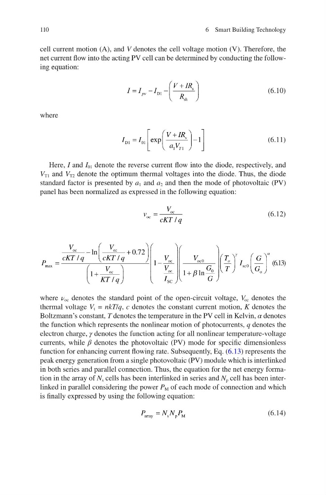
net current flow into the acting PV cell can be determined by conducting the following equation:
I I
I
V IR
R
§
©
¨
·
¹
¸
pv
D
s
sh
1
(6.10)
where
I
I
V IR
a V T
D
s
1
0 1
1
1
1
§
©
¨
·
¹
¸
ª
¬
«
«
º
¼
»
»
exp
(6.11)
Here, I and I 01 denote the reverse current flow into the diode, respectively, and
V T1 and V T2 denote the optimum thermal voltages into the diode. Thus, the diode
standard factor is presented by a 1 and a 2 and then the mode of photovoltaic (PV)
panel has been normalized as expressed in the following equation:
v
V
cKT q
oc
oc
=
/
(6.12)
P
V
cKT q
V
cKT q
V
KT q
V
V
max
/
ln
/
.
/
§
©
¨
·
¹
¸
§
©
¨
·
¹
¸
oc
oc
oc
oc
oc
0 72
1
1
I I
V
G
G
T
T
I
G
G
o
SC
oc
sc
o
§
©
¨
¨
¨
¨
·
¹
¸
¸
¸
¸
§
©
¨
¨
¨ ¨
·
¹
¸
¸
¸ ¸
§
©
¨
·
¹
¸
§
0
0
0
1 E ln
J
© ©
¨
·
¹
¸
D
(6.13)
where ν oc denotes the standard point of the open-circuit voltage, V oc denotes the
thermal voltage V t = nkT/q, c denotes the constant current motion, K denotes the
Boltzmann’s constant, T denotes the temperature in the PV cell in Kelvin, α denotes
the function which represents the nonlinear motion of photocurrents, q denotes the
electron charge, γ denotes the function acting for all nonlinear temperature-voltage
currents, while β denotes the photovoltaic (PV) mode for specific dimensionless
function for enhancing current flowing rate. Subsequently, Eq. (6.13) represents the
peak energy generation from a single photovoltaic (PV) module which is interlinked
in both series and parallel connection. Thus, the equation for the net energy formation in the array of N s cells has been interlinked in series and N p cell has been interlinked in parallel considering the power P M of each mode of connection and which
is finally expressed by using the following equation:
P
N N P
array
s p M
=
(6.14)
6 Smart Building Technology
cell current motion (A), and V denotes the cell voltage motion (V). Therefore, the
net current flow into the acting PV cell can be determined by conducting the following equation:
I I
I
V IR
R
§
©
¨
·
¹
¸
pv
D
s
sh
1
(6.10)
where
I
I
V IR
a V T
D
s
1
0 1
1
1
1
§
©
¨
·
¹
¸
ª
¬
«
«
º
¼
»
»
exp
(6.11)
Here, I and I 01 denote the reverse current flow into the diode, respectively, and
V T1 and V T2 denote the optimum thermal voltages into the diode. Thus, the diode
standard factor is presented by a 1 and a 2 and then the mode of photovoltaic (PV)
panel has been normalized as expressed in the following equation:
v
V
cKT q
oc
oc
=
/
(6.12)
P
V
cKT q
V
cKT q
V
KT q
V
V
max
/
ln
/
.
/
§
©
¨
·
¹
¸
§
©
¨
·
¹
¸
oc
oc
oc
oc
oc
0 72
1
1
I I
V
G
G
T
T
I
G
G
o
SC
oc
sc
o
§
©
¨
¨
¨
¨
·
¹
¸
¸
¸
¸
§
©
¨
¨
¨ ¨
·
¹
¸
¸
¸ ¸
§
©
¨
·
¹
¸
§
0
0
0
1 E ln
J
© ©
¨
·
¹
¸
D
(6.13)
where ν oc denotes the standard point of the open-circuit voltage, V oc denotes the
thermal voltage V t = nkT/q, c denotes the constant current motion, K denotes the
Boltzmann’s constant, T denotes the temperature in the PV cell in Kelvin, α denotes
the function which represents the nonlinear motion of photocurrents, q denotes the
electron charge, γ denotes the function acting for all nonlinear temperature-voltage
currents, while β denotes the photovoltaic (PV) mode for specific dimensionless
function for enhancing current flowing rate. Subsequently, Eq. (6.13) represents the
peak energy generation from a single photovoltaic (PV) module which is interlinked
in both series and parallel connection. Thus, the equation for the net energy formation in the array of N s cells has been interlinked in series and N p cell has been interlinked in parallel considering the power P M of each mode of connection and which
is finally expressed by using the following equation:
P
N N P
array
s p M
=
(6.14)
6 Smart Building Technology