

108
Hence, the following equation is calculated as the energy deliberation from a
photovoltaic (PV) panel, which origin is the photon irradiance and ambient temperature of the acting PV panel:
P
A G
pv
pvg
pvg
t
K
(6.1)
Here, η pvg denotes the PV performance rate, A pvg denotes the PV generator array
(m
2
), and G t denotes the photon irradiance intake rate on the plane (W/m
2
) of acting
PV panel and thus η pvg could be rewritten as follows:
K
KK
E
pvg
r pc
c
cref
ª ¬
º ¼
1
T T
(6.2)
η pc denotes the energy formation efficiency, when maximum power point tracking (MPPT) is implemented which is close to 1. Here β denotes the temperature
cofactor (0.004–0.006 per °C); η r denotes the mode of energy efficiency; and T cref
denotes the condition of temperature at °C. The reference cell temperature (T cref ) can
be determined by calculating from the equation below:
T T
G
c
a
t
NOCT
§
©
¨
·
¹
¸
20
800
(6.3)
T a denotes the ambient temperature in °C, and G t denotes the solar radiation in
the active PV panel (W/m
2
), and thus it denotes the modest optimum cell temperature in °C. Considering this temperature condition, the net solar radiation in acting
PV cell can be calculated by the equation below:
I I R I R
I I R
t
b b
d d
b
d
r
(6.4)
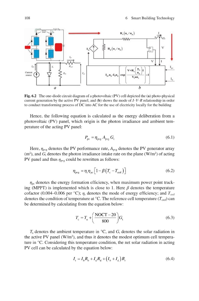
Fig. 6.2 The one-diode circuit diagram of a photovoltaic (PV) cell depicted the (a) photo-physical
current generation by the active PV panel, and (b) shows the mode of I–V–R relationship in order
to conduct transforming process of DC into AC for the use of electricity locally for the building
6 Smart Building Technology
Hence, the following equation is calculated as the energy deliberation from a
photovoltaic (PV) panel, which origin is the photon irradiance and ambient temperature of the acting PV panel:
P
A G
pv
pvg
pvg
t
K
(6.1)
Here, η pvg denotes the PV performance rate, A pvg denotes the PV generator array
(m
2
), and G t denotes the photon irradiance intake rate on the plane (W/m
2
) of acting
PV panel and thus η pvg could be rewritten as follows:
K
KK
E
pvg
r pc
c
cref
ª ¬
º ¼
1
T T
(6.2)
η pc denotes the energy formation efficiency, when maximum power point tracking (MPPT) is implemented which is close to 1. Here β denotes the temperature
cofactor (0.004–0.006 per °C); η r denotes the mode of energy efficiency; and T cref
denotes the condition of temperature at °C. The reference cell temperature (T cref ) can
be determined by calculating from the equation below:
T T
G
c
a
t
NOCT
§
©
¨
·
¹
¸
20
800
(6.3)
T a denotes the ambient temperature in °C, and G t denotes the solar radiation in
the active PV panel (W/m
2
), and thus it denotes the modest optimum cell temperature in °C. Considering this temperature condition, the net solar radiation in acting
PV cell can be calculated by the equation below:
I I R I R
I I R
t
b b
d d
b
d
r
(6.4)
Fig. 6.2 The one-diode circuit diagram of a photovoltaic (PV) cell depicted the (a) photo-physical
current generation by the active PV panel, and (b) shows the mode of I–V–R relationship in order
to conduct transforming process of DC into AC for the use of electricity locally for the building
6 Smart Building Technology