

58
2 Methods for Investigating Electro-Chemo-Mechanical …
where i o is the current density amplitude and ψ e is the phase angle between current and
potential. Similarly, the corresponding surface stress response, i.e., the mechanical
response, of the cantilever electrode is given by
g = g dc + g o exp
j(ωt + ψ s )
,
(2.34)
where g o is the surface stress amplitude and ψ s is the phase angle between surface
stress g and potential E.
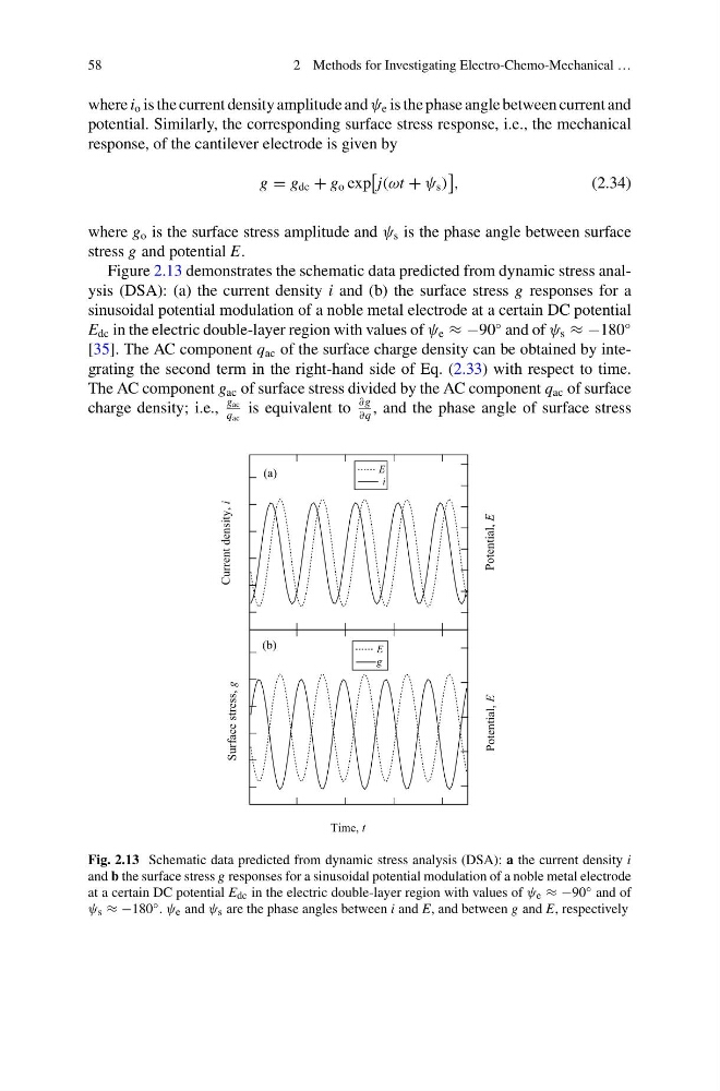
Figure 2.13 demonstrates the schematic data predicted from dynamic stress analysis (DSA): (a) the current density i and (b) the surface stress g responses for a
sinusoidal potential modulation of a noble metal electrode at a certain DC potential
E dc in the electric double-layer region with values of ψ e ≈ −90
◦ and of ψ s ≈ −180
◦
[35]. The AC component q ac of the surface charge density can be obtained by integrating the second term in the right-hand side of Eq. (2.33) with respect to time.
The AC component g ac of surface stress divided by the AC component q ac of surface
charge density; i.e.,
g ac
q ac
is equivalent to
∂g
∂q
, and the phase angle of surface stress
Surface stress,
Time, t
Potential,
E
E
g
(b)
Current density,
i
Potential,
E
E
i
(a)
g
Fig. 2.13 Schematic data predicted from dynamic stress analysis (DSA): a the current density i
and b the surface stress g responses for a sinusoidal potential modulation of a noble metal electrode
at a certain DC potential E dc in the electric double-layer region with values of ψ e ≈ −90 ◦ and of
ψ s ≈ −180 ◦ . ψ e and ψ s are the phase angles between i and E, and between g and E, respectively
2 Methods for Investigating Electro-Chemo-Mechanical …
where i o is the current density amplitude and ψ e is the phase angle between current and
potential. Similarly, the corresponding surface stress response, i.e., the mechanical
response, of the cantilever electrode is given by
g = g dc + g o exp
j(ωt + ψ s )
,
(2.34)
where g o is the surface stress amplitude and ψ s is the phase angle between surface
stress g and potential E.
Figure 2.13 demonstrates the schematic data predicted from dynamic stress analysis (DSA): (a) the current density i and (b) the surface stress g responses for a
sinusoidal potential modulation of a noble metal electrode at a certain DC potential
E dc in the electric double-layer region with values of ψ e ≈ −90
◦ and of ψ s ≈ −180
◦
[35]. The AC component q ac of the surface charge density can be obtained by integrating the second term in the right-hand side of Eq. (2.33) with respect to time.
The AC component g ac of surface stress divided by the AC component q ac of surface
charge density; i.e.,
g ac
q ac
is equivalent to
∂g
∂q
, and the phase angle of surface stress
Surface stress,
Time, t
Potential,
E
E
g
(b)
Current density,
i
Potential,
E
E
i
(a)
g
Fig. 2.13 Schematic data predicted from dynamic stress analysis (DSA): a the current density i
and b the surface stress g responses for a sinusoidal potential modulation of a noble metal electrode
at a certain DC potential E dc in the electric double-layer region with values of ψ e ≈ −90 ◦ and of
ψ s ≈ −180 ◦ . ψ e and ψ s are the phase angles between i and E, and between g and E, respectively