

148
7 Virtual testing approach for sandwich panel joints
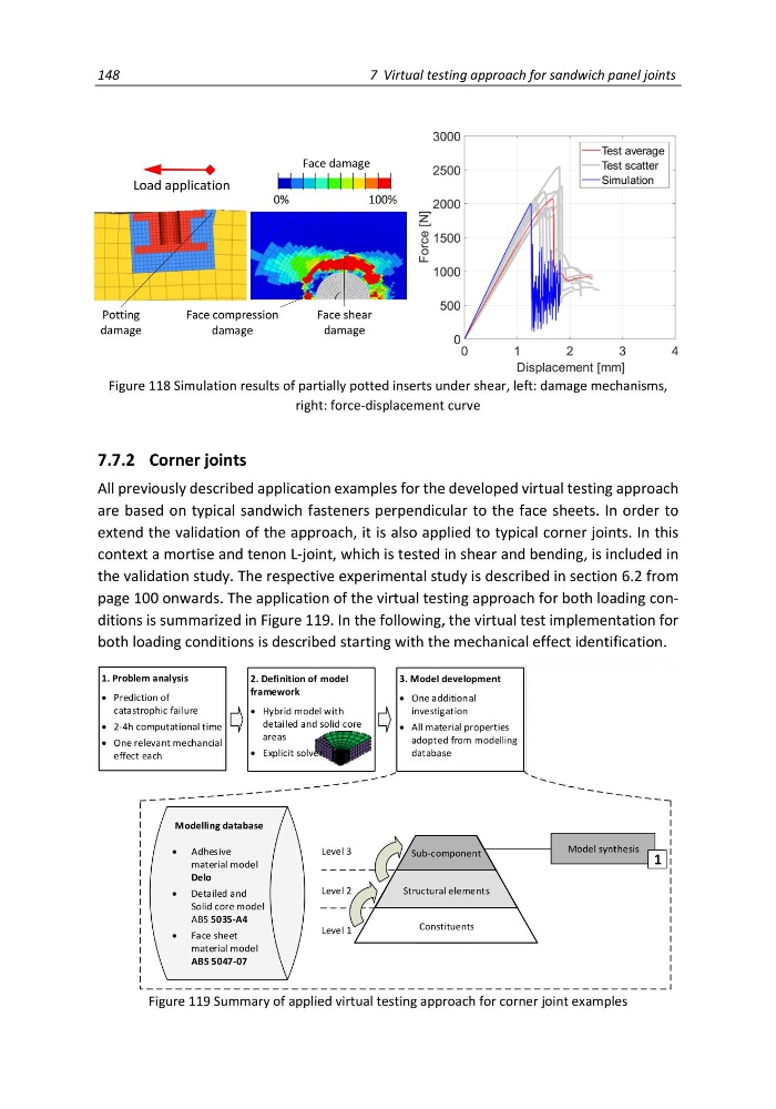
Figure 118 Simulation results of partially potted inserts under shear, left: damage mechanisms,
right: force-displacement curve
7.7.2 Corner joints
All previously described application examples for the developed virtual testing approach
are based on typical sandwich fasteners perpendicular to the face sheets. In order to
extend the validation of the approach, it is also applied to typical corner joints. In this
context a mortise and tenon L-joint, which is tested in shear and bending, is included in
the validation study. The respective experimental study is described in section 6.2 from
page 100 onwards. The application of the virtual testing approach for both loading conditions is summarized in Figure 119. In the following, the virtual test implementation for
both loading conditions is described starting with the mechanical effect identification.
2. Definition of model
framework
Hybrid model with
detailed and solid core
areas
Explicit solver
1. Problem analysis
Prediction of
catastrophic failure
2-4h computational time
One relevant mechancial
effect each
3. Model development
One additional
investigation
All material properties
adopted from modelling
database
4. Application of virtual
test method
Parameter studies
Evaluation of design
alternatives
Structural elements
Constituents
Level 1
Level 2
Level 3
Model synthesis
Constituents
Structural elements
Sub-component
Modelling database
Adhesive
material model
Delo
Detailed and
Solid core model
ABS 5035-A4
Face sheet
material model
ABS 5047-07
1
Figure 119 Summary of applied virtual testing approach for corner joint examples
Load application
Potting
damage
Face shear
damage
Face compression
damage
Face damage
0%
100%
7 Virtual testing approach for sandwich panel joints
Figure 118 Simulation results of partially potted inserts under shear, left: damage mechanisms,
right: force-displacement curve
7.7.2 Corner joints
All previously described application examples for the developed virtual testing approach
are based on typical sandwich fasteners perpendicular to the face sheets. In order to
extend the validation of the approach, it is also applied to typical corner joints. In this
context a mortise and tenon L-joint, which is tested in shear and bending, is included in
the validation study. The respective experimental study is described in section 6.2 from
page 100 onwards. The application of the virtual testing approach for both loading conditions is summarized in Figure 119. In the following, the virtual test implementation for
both loading conditions is described starting with the mechanical effect identification.
2. Definition of model
framework
Hybrid model with
detailed and solid core
areas
Explicit solver
1. Problem analysis
Prediction of
catastrophic failure
2-4h computational time
One relevant mechancial
effect each
3. Model development
One additional
investigation
All material properties
adopted from modelling
database
4. Application of virtual
test method
Parameter studies
Evaluation of design
alternatives
Structural elements
Constituents
Level 1
Level 2
Level 3
Model synthesis
Constituents
Structural elements
Sub-component
Modelling database
Adhesive
material model
Delo
Detailed and
Solid core model
ABS 5035-A4
Face sheet
material model
ABS 5047-07
1
Figure 119 Summary of applied virtual testing approach for corner joint examples
Load application
Potting
damage
Face shear
damage
Face compression
damage
Face damage
0%
100%