

7.7 Validation based on different joint configurations
147
The second investigation is the synthesis of the top-level model. This investigation has
been characterized by numerical studies regarding mesh size and boundary conditions.
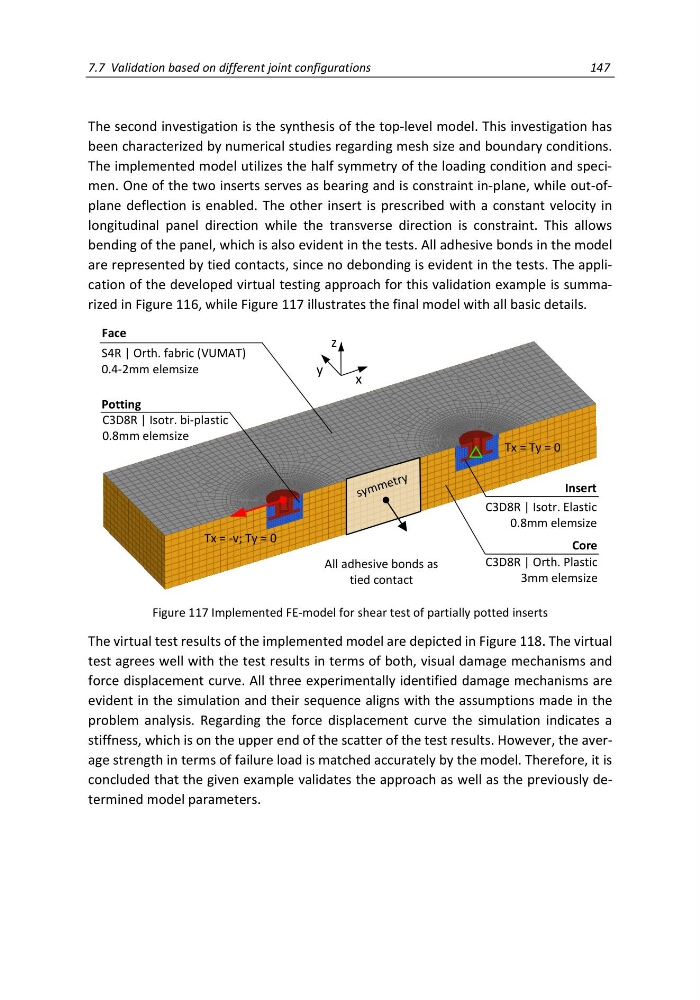
The implemented model utilizes the half symmetry of the loading condition and specimen. One of the two inserts serves as bearing and is constraint in-plane, while out-ofplane deflection is enabled. The other insert is prescribed with a constant velocity in
longitudinal panel direction while the transverse direction is constraint. This allows
bending of the panel, which is also evident in the tests. All adhesive bonds in the model
are represented by tied contacts, since no debonding is evident in the tests. The application of the developed virtual testing approach for this validation example is summarized in Figure 116, while Figure 117 illustrates the final model with all basic details.
Figure 117 Implemented FE-model for shear test of partially potted inserts
The virtual test results of the implemented model are depicted in Figure 118. The virtual
test agrees well with the test results in terms of both, visual damage mechanisms and
force displacement curve. All three experimentally identified damage mechanisms are
evident in the simulation and their sequence aligns with the assumptions made in the
problem analysis. Regarding the force displacement curve the simulation indicates a
stiffness, which is on the upper end of the scatter of the test results. However, the average strength in terms of failure load is matched accurately by the model. Therefore, it is
concluded that the given example validates the approach as well as the previously determined model parameters.
S4R | Orth. fabric (VUMAT)
0.4-2mm elemsize
Face
Potting
C3D8R | Isotr. bi-plastic
0.8mm elemsize
C3D8R | Isotr. Elastic
0.8mm elemsize
Insert
Core
C3D8R | Orth. Plastic
3mm elemsize
All adhesive bonds as
tied contact
Tx = Ty = 0
y
x
z
Tx = -v; Ty = 0
147
The second investigation is the synthesis of the top-level model. This investigation has
been characterized by numerical studies regarding mesh size and boundary conditions.
The implemented model utilizes the half symmetry of the loading condition and specimen. One of the two inserts serves as bearing and is constraint in-plane, while out-ofplane deflection is enabled. The other insert is prescribed with a constant velocity in
longitudinal panel direction while the transverse direction is constraint. This allows
bending of the panel, which is also evident in the tests. All adhesive bonds in the model
are represented by tied contacts, since no debonding is evident in the tests. The application of the developed virtual testing approach for this validation example is summarized in Figure 116, while Figure 117 illustrates the final model with all basic details.
Figure 117 Implemented FE-model for shear test of partially potted inserts
The virtual test results of the implemented model are depicted in Figure 118. The virtual
test agrees well with the test results in terms of both, visual damage mechanisms and
force displacement curve. All three experimentally identified damage mechanisms are
evident in the simulation and their sequence aligns with the assumptions made in the
problem analysis. Regarding the force displacement curve the simulation indicates a
stiffness, which is on the upper end of the scatter of the test results. However, the average strength in terms of failure load is matched accurately by the model. Therefore, it is
concluded that the given example validates the approach as well as the previously determined model parameters.
S4R | Orth. fabric (VUMAT)
0.4-2mm elemsize
Face
Potting
C3D8R | Isotr. bi-plastic
0.8mm elemsize
C3D8R | Isotr. Elastic
0.8mm elemsize
Insert
Core
C3D8R | Orth. Plastic
3mm elemsize
All adhesive bonds as
tied contact
Tx = Ty = 0
y
x
z
Tx = -v; Ty = 0