

132
7 Virtual testing approach for sandwich panel joints
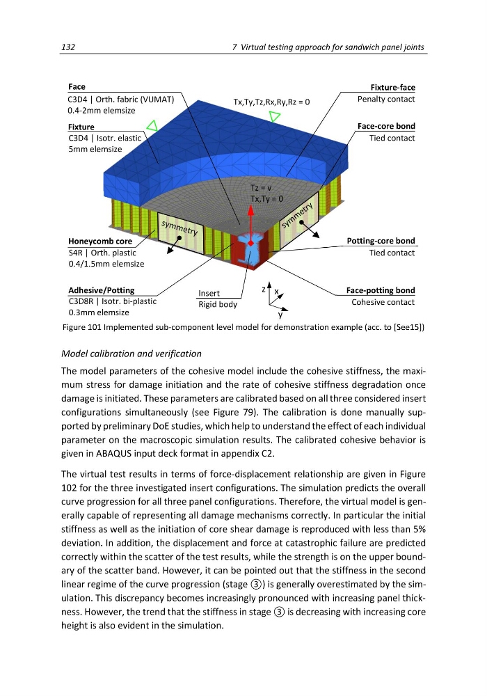
Figure 101 Implemented sub-component level model for demonstration example (acc. to [See15])
Model calibration and verification
The model parameters of the cohesive model include the cohesive stiffness, the maximum stress for damage initiation and the rate of cohesive stiffness degradation once
damage is initiated. These parameters are calibrated based on all three considered insert
configurations simultaneously (see Figure 79). The calibration is done manually supported by preliminary DoE studies, which help to understand the effect of each individual
parameter on the macroscopic simulation results. The calibrated cohesive behavior is
given in ABAQUS input deck format in appendix C2.
The virtual test results in terms of force-displacement relationship are given in Figure
102 for the three investigated insert configurations. The simulation predicts the overall
curve progression for all three panel configurations. Therefore, the virtual model is generally capable of representing all damage mechanisms correctly. In particular the initial
stiffness as well as the initiation of core shear damage is reproduced with less than 5%
deviation. In addition, the displacement and force at catastrophic failure are predicted
correctly within the scatter of the test results, while the strength is on the upper boundary of the scatter band. However, it can be pointed out that the stiffness in the second
linear regime of the curve progression (stage ③) is generally overestimated by the simulation. This discrepancy becomes increasingly pronounced with increasing panel thickness. However, the trend that the stiffness in stage ③ is decreasing with increasing core
height is also evident in the simulation.
Insert
Rigid body
Face-core bond
Tied contact
Fixture-face
Penalty contact
y
x
z
Honeycomb core
S4R | Orth. plastic
0.4/1.5mm elemsize
Fixture
C3D4 | Isotr. elastic
5mm elemsize
Adhesive/Potting
C3D8R | Isotr. bi-plastic
0.3mm elemsize
Face
C3D4 | Orth. fabric (VUMAT)
0.4-2mm elemsize
Tx,Ty,Tz,Rx,Ry,Rz = 0
Tz = v
Tx,Ty = 0
Face-potting bond
Cohesive contact
Potting-core bond
Tied contact
7 Virtual testing approach for sandwich panel joints
Figure 101 Implemented sub-component level model for demonstration example (acc. to [See15])
Model calibration and verification
The model parameters of the cohesive model include the cohesive stiffness, the maximum stress for damage initiation and the rate of cohesive stiffness degradation once
damage is initiated. These parameters are calibrated based on all three considered insert
configurations simultaneously (see Figure 79). The calibration is done manually supported by preliminary DoE studies, which help to understand the effect of each individual
parameter on the macroscopic simulation results. The calibrated cohesive behavior is
given in ABAQUS input deck format in appendix C2.
The virtual test results in terms of force-displacement relationship are given in Figure
102 for the three investigated insert configurations. The simulation predicts the overall
curve progression for all three panel configurations. Therefore, the virtual model is generally capable of representing all damage mechanisms correctly. In particular the initial
stiffness as well as the initiation of core shear damage is reproduced with less than 5%
deviation. In addition, the displacement and force at catastrophic failure are predicted
correctly within the scatter of the test results, while the strength is on the upper boundary of the scatter band. However, it can be pointed out that the stiffness in the second
linear regime of the curve progression (stage ③) is generally overestimated by the simulation. This discrepancy becomes increasingly pronounced with increasing panel thickness. However, the trend that the stiffness in stage ③ is decreasing with increasing core
height is also evident in the simulation.
Insert
Rigid body
Face-core bond
Tied contact
Fixture-face
Penalty contact
y
x
z
Honeycomb core
S4R | Orth. plastic
0.4/1.5mm elemsize
Fixture
C3D4 | Isotr. elastic
5mm elemsize
Adhesive/Potting
C3D8R | Isotr. bi-plastic
0.3mm elemsize
Face
C3D4 | Orth. fabric (VUMAT)
0.4-2mm elemsize
Tx,Ty,Tz,Rx,Ry,Rz = 0
Tz = v
Tx,Ty = 0
Face-potting bond
Cohesive contact
Potting-core bond
Tied contact