

7.4 Phase 3 - Model development
131
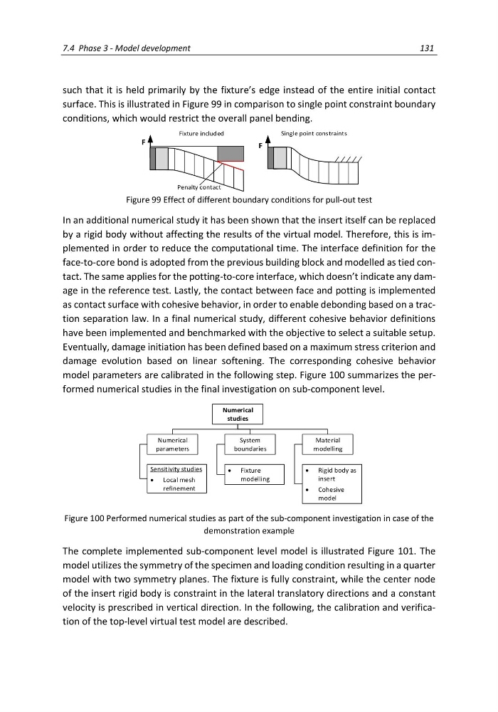
such that it is held primarily by the fixture’s edge instead of the entire initial contact
surface. This is illustrated in Figure 99 in comparison to single point constraint boundary
conditions, which would restrict the overall panel bending.
Fixture included
Single point constraints
F
F
Penalty contact
Figure 99 Effect of different boundary conditions for pull-out test
In an additional numerical study it has been shown that the insert itself can be replaced
by a rigid body without affecting the results of the virtual model. Therefore, this is implemented in order to reduce the computational time. The interface definition for the
face-to-core bond is adopted from the previous building block and modelled as tied contact. The same applies for the potting-to-core interface, which doesn’t indicate any damage in the reference test. Lastly, the contact between face and potting is implemented
as contact surface with cohesive behavior, in order to enable debonding based on a traction separation law. In a final numerical study, different cohesive behavior definitions
have been implemented and benchmarked with the objective to select a suitable setup.
Eventually, damage initiation has been defined based on a maximum stress criterion and
damage evolution based on linear softening. The corresponding cohesive behavior
model parameters are calibrated in the following step. Figure 100 summarizes the performed numerical studies in the final investigation on sub-component level.
Figure 100 Performed numerical studies as part of the sub-component investigation in case of the
demonstration example
The complete implemented sub-component level model is illustrated Figure 101. The
model utilizes the symmetry of the specimen and loading condition resulting in a quarter
model with two symmetry planes. The fixture is fully constraint, while the center node
of the insert rigid body is constraint in the lateral translatory directions and a constant
velocity is prescribed in vertical direction. In the following, the calibration and verification of the top-level virtual test model are described.
Material
modelling
Numerical
parameters
System
boundaries
Numerical
studies
Sensitivity studies
Local mesh
refinement
Fixture
modelling
Rigid body as
insert
Cohesive
model
131
such that it is held primarily by the fixture’s edge instead of the entire initial contact
surface. This is illustrated in Figure 99 in comparison to single point constraint boundary
conditions, which would restrict the overall panel bending.
Fixture included
Single point constraints
F
F
Penalty contact
Figure 99 Effect of different boundary conditions for pull-out test
In an additional numerical study it has been shown that the insert itself can be replaced
by a rigid body without affecting the results of the virtual model. Therefore, this is implemented in order to reduce the computational time. The interface definition for the
face-to-core bond is adopted from the previous building block and modelled as tied contact. The same applies for the potting-to-core interface, which doesn’t indicate any damage in the reference test. Lastly, the contact between face and potting is implemented
as contact surface with cohesive behavior, in order to enable debonding based on a traction separation law. In a final numerical study, different cohesive behavior definitions
have been implemented and benchmarked with the objective to select a suitable setup.
Eventually, damage initiation has been defined based on a maximum stress criterion and
damage evolution based on linear softening. The corresponding cohesive behavior
model parameters are calibrated in the following step. Figure 100 summarizes the performed numerical studies in the final investigation on sub-component level.
Figure 100 Performed numerical studies as part of the sub-component investigation in case of the
demonstration example
The complete implemented sub-component level model is illustrated Figure 101. The
model utilizes the symmetry of the specimen and loading condition resulting in a quarter
model with two symmetry planes. The fixture is fully constraint, while the center node
of the insert rigid body is constraint in the lateral translatory directions and a constant
velocity is prescribed in vertical direction. In the following, the calibration and verification of the top-level virtual test model are described.
Material
modelling
Numerical
parameters
System
boundaries
Numerical
studies
Sensitivity studies
Local mesh
refinement
Fixture
modelling
Rigid body as
insert
Cohesive
model