

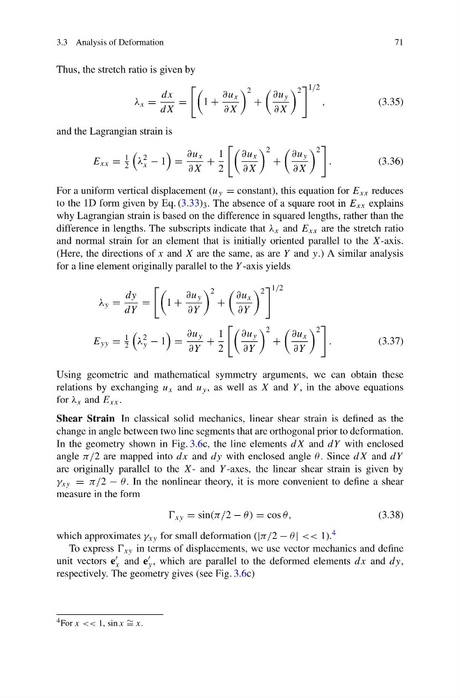
3.3 Analysis of Deformation
71
Thus, the stretch ratio is given by
λ x =
dx
dX
=
1 +
∂u x
∂X
2
+
∂u y
∂X
2
1/2
,
(3.35)
and the Lagrangian strain is
E xx =
1
2
λ
2
x − 1
=
∂u x
∂X
+
1
2
∂u x
∂X
2
+
∂u y
∂X
2
.
(3.36)
For a uniform vertical displacement (u y = constant), this equation for E xx reduces
to the 1D form given by Eq. (3.33) 3 . The absence of a square root in E xx explains
why Lagrangian strain is based on the difference in squared lengths, rather than the
difference in lengths. The subscripts indicate that λ x and E xx are the stretch ratio
and normal strain for an element that is initially oriented parallel to the X-axis.
(Here, the directions of x and X are the same, as are Y and y.) A similar analysis
for a line element originally parallel to the Y -axis yields
λ y =
dy
dY
=
1 +
∂u y
∂Y
2
+
∂u x
∂Y
2
1/2
E yy =
1
2
λ
2
y − 1
=
∂u y
∂Y
+
1
2
∂u y
∂Y
2
+
∂u x
∂Y
2
.
(3.37)
Using geometric and mathematical symmetry arguments, we can obtain these
relations by exchanging u x and u y , as well as X and Y , in the above equations
for λ x and E xx .
Shear Strain In classical solid mechanics, linear shear strain is defined as the
change in angle between two line segments that are orthogonal prior to deformation.
In the geometry shown in Fig. 3.6c, the line elements dX and dY with enclosed
angle π/2 are mapped into dx and dy with enclosed angle θ . Since dX and dY
are originally parallel to the X- and Y -axes, the linear shear strain is given by
γ xy = π/2 − θ . In the nonlinear theory, it is more convenient to define a shear
measure in the form
xy = sin(π/2 − θ) = cos θ,
(3.38)
which approximates γ xy for small deformation (|π/2 − θ | << 1). 4
To express xy in terms of displacements, we use vector mechanics and define
unit vectors e
x and e
y , which are parallel to the deformed elements dx and dy,
respectively. The geometry gives (see Fig. 3.6c)
4 For x << 1, sin x ∼ = x.
71
Thus, the stretch ratio is given by
λ x =
dx
dX
=
1 +
∂u x
∂X
2
+
∂u y
∂X
2
1/2
,
(3.35)
and the Lagrangian strain is
E xx =
1
2
λ
2
x − 1
=
∂u x
∂X
+
1
2
∂u x
∂X
2
+
∂u y
∂X
2
.
(3.36)
For a uniform vertical displacement (u y = constant), this equation for E xx reduces
to the 1D form given by Eq. (3.33) 3 . The absence of a square root in E xx explains
why Lagrangian strain is based on the difference in squared lengths, rather than the
difference in lengths. The subscripts indicate that λ x and E xx are the stretch ratio
and normal strain for an element that is initially oriented parallel to the X-axis.
(Here, the directions of x and X are the same, as are Y and y.) A similar analysis
for a line element originally parallel to the Y -axis yields
λ y =
dy
dY
=
1 +
∂u y
∂Y
2
+
∂u x
∂Y
2
1/2
E yy =
1
2
λ
2
y − 1
=
∂u y
∂Y
+
1
2
∂u y
∂Y
2
+
∂u x
∂Y
2
.
(3.37)
Using geometric and mathematical symmetry arguments, we can obtain these
relations by exchanging u x and u y , as well as X and Y , in the above equations
for λ x and E xx .
Shear Strain In classical solid mechanics, linear shear strain is defined as the
change in angle between two line segments that are orthogonal prior to deformation.
In the geometry shown in Fig. 3.6c, the line elements dX and dY with enclosed
angle π/2 are mapped into dx and dy with enclosed angle θ . Since dX and dY
are originally parallel to the X- and Y -axes, the linear shear strain is given by
γ xy = π/2 − θ . In the nonlinear theory, it is more convenient to define a shear
measure in the form
xy = sin(π/2 − θ) = cos θ,
(3.38)
which approximates γ xy for small deformation (|π/2 − θ | << 1). 4
To express xy in terms of displacements, we use vector mechanics and define
unit vectors e
x and e
y , which are parallel to the deformed elements dx and dy,
respectively. The geometry gives (see Fig. 3.6c)
4 For x << 1, sin x ∼ = x.