

70
3 Continuum Mechanics and Nonlinear Elasticity
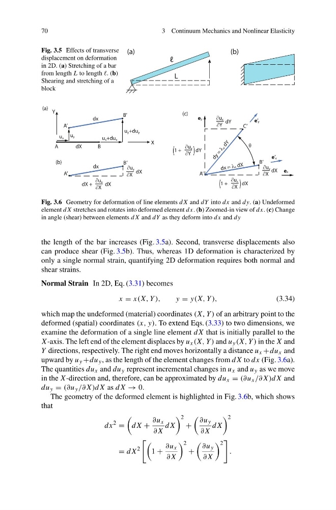
Fig. 3.5 Effects of transverse
displacement on deformation
in 2D. (a) Stretching of a bar
from length L to length . (b)
Shearing and stretching of a
block
L
(a)
(b)
ℓ
dX
u x +du x
u y +du y
dx
A
B
A’
B’
u x u y
X
Y
(a)
dx = Ox dX
A’
B’
wu y
wX
dX
(b)
dx
A’
B’
dX +
wu x
wX
dX
wu y
wX
dX
1 +
wu x
wX
dX
(
)
1 +
wu y
wY
dY
(
)
wu x
wY
dY
d y =
O y
d Y
C’
ex
e’x
e’y
ey
T
(c)
Fig. 3.6 Geometry for deformation of line elements dX and dY into dx and dy. (a) Undeformed
element dX stretches and rotates into deformed element dx. (b) Zoomed-in view of dx. (c) Change
in angle (shear) between elements dX and dY as they deform into dx and dy
the length of the bar increases (Fig. 3.5a). Second, transverse displacements also
can produce shear (Fig. 3.5b). Thus, whereas 1D deformation is characterized by
only a single normal strain, quantifying 2D deformation requires both normal and
shear strains.
Normal Strain In 2D, Eq. (3.31) becomes
x = x(X, Y ),
y = y(X, Y ),
(3.34)
which map the undeformed (material) coordinates (X, Y ) of an arbitrary point to the
deformed (spatial) coordinates (x, y). To extend Eqs. (3.33) to two dimensions, we
examine the deformation of a single line element dX that is initially parallel to the
X-axis. The left end of the element displaces by u x (X, Y ) and u y (X, Y ) in the X and
Y directions, respectively. The right end moves horizontally a distance u x +du x and
upward by u y +du y , as the length of the element changes from dX to dx (Fig. 3.6a).
The quantities du x and du y represent incremental changes in u x and u y as we move
in the X-direction and, therefore, can be approximated by du x = (∂u x /∂X)dX and
du y = (∂u y /∂X)dX as dX → 0.
The geometry of the deformed element is highlighted in Fig. 3.6b, which shows
that
dx
2
=
dX +
∂u x
∂X
dX
2
+
∂u y
∂X
dX
2
= dX
2
1 +
∂u x
∂X
2
+
∂u y
∂X
2
.
3 Continuum Mechanics and Nonlinear Elasticity
Fig. 3.5 Effects of transverse
displacement on deformation
in 2D. (a) Stretching of a bar
from length L to length . (b)
Shearing and stretching of a
block
L
(a)
(b)
ℓ
dX
u x +du x
u y +du y
dx
A
B
A’
B’
u x u y
X
Y
(a)
dx = Ox dX
A’
B’
wu y
wX
dX
(b)
dx
A’
B’
dX +
wu x
wX
dX
wu y
wX
dX
1 +
wu x
wX
dX
(
)
1 +
wu y
wY
dY
(
)
wu x
wY
dY
d y =
O y
d Y
C’
ex
e’x
e’y
ey
T
(c)
Fig. 3.6 Geometry for deformation of line elements dX and dY into dx and dy. (a) Undeformed
element dX stretches and rotates into deformed element dx. (b) Zoomed-in view of dx. (c) Change
in angle (shear) between elements dX and dY as they deform into dx and dy
the length of the bar increases (Fig. 3.5a). Second, transverse displacements also
can produce shear (Fig. 3.5b). Thus, whereas 1D deformation is characterized by
only a single normal strain, quantifying 2D deformation requires both normal and
shear strains.
Normal Strain In 2D, Eq. (3.31) becomes
x = x(X, Y ),
y = y(X, Y ),
(3.34)
which map the undeformed (material) coordinates (X, Y ) of an arbitrary point to the
deformed (spatial) coordinates (x, y). To extend Eqs. (3.33) to two dimensions, we
examine the deformation of a single line element dX that is initially parallel to the
X-axis. The left end of the element displaces by u x (X, Y ) and u y (X, Y ) in the X and
Y directions, respectively. The right end moves horizontally a distance u x +du x and
upward by u y +du y , as the length of the element changes from dX to dx (Fig. 3.6a).
The quantities du x and du y represent incremental changes in u x and u y as we move
in the X-direction and, therefore, can be approximated by du x = (∂u x /∂X)dX and
du y = (∂u y /∂X)dX as dX → 0.
The geometry of the deformed element is highlighted in Fig. 3.6b, which shows
that
dx
2
=
dX +
∂u x
∂X
dX
2
+
∂u y
∂X
dX
2
= dX
2
1 +
∂u x
∂X
2
+
∂u y
∂X
2
.