

438
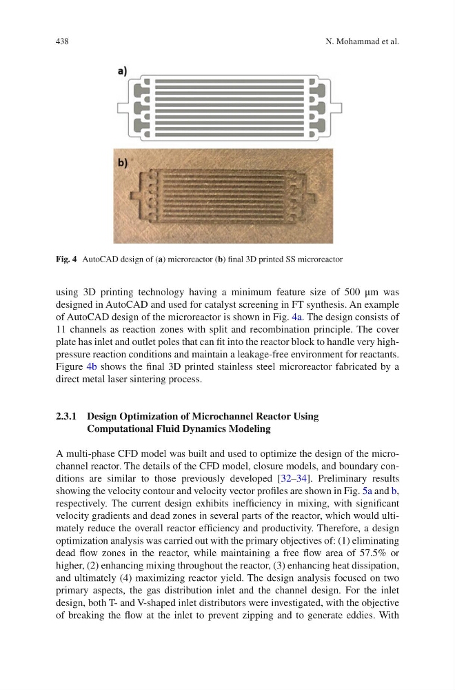
using 3D printing technology having a minimum feature size of 500 μm was
designed in AutoCAD and used for catalyst screening in FT synthesis. An example
of AutoCAD design of the microreactor is shown in Fig. 4a. The design consists of
11 channels as reaction zones with split and recombination principle. The cover
plate has inlet and outlet poles that can fit into the reactor block to handle very highpressure reaction conditions and maintain a leakage-free environment for reactants.
Figure 4b shows the final 3D printed stainless steel microreactor fabricated by a
direct metal laser sintering process.
2.3.1 Design Optimization of Microchannel Reactor Using
Computational Fluid Dynamics Modeling
A multi-phase CFD model was built and used to optimize the design of the microchannel reactor. The details of the CFD model, closure models, and boundary conditions are similar to those previously developed [32–34]. Preliminary results
showing the velocity contour and velocity vector profiles are shown in Fig. 5a and b,
respectively. The current design exhibits inefficiency in mixing, with significant
velocity gradients and dead zones in several parts of the reactor, which would ultimately reduce the overall reactor efficiency and productivity. Therefore, a design
optimization analysis was carried out with the primary objectives of: (1) eliminating
dead flow zones in the reactor, while maintaining a free flow area of 57.5% or
higher, (2) enhancing mixing throughout the reactor, (3) enhancing heat dissipation,
and ultimately (4) maximizing reactor yield. The design analysis focused on two
primary aspects, the gas distribution inlet and the channel design. For the inlet
design, both T- and V-shaped inlet distributors were investigated, with the objective
of breaking the flow at the inlet to prevent zipping and to generate eddies. With
Fig. 4 AutoCAD design of (a) microreactor (b) final 3D printed SS microreactor
N. Mohammad et al.
using 3D printing technology having a minimum feature size of 500 μm was
designed in AutoCAD and used for catalyst screening in FT synthesis. An example
of AutoCAD design of the microreactor is shown in Fig. 4a. The design consists of
11 channels as reaction zones with split and recombination principle. The cover
plate has inlet and outlet poles that can fit into the reactor block to handle very highpressure reaction conditions and maintain a leakage-free environment for reactants.
Figure 4b shows the final 3D printed stainless steel microreactor fabricated by a
direct metal laser sintering process.
2.3.1 Design Optimization of Microchannel Reactor Using
Computational Fluid Dynamics Modeling
A multi-phase CFD model was built and used to optimize the design of the microchannel reactor. The details of the CFD model, closure models, and boundary conditions are similar to those previously developed [32–34]. Preliminary results
showing the velocity contour and velocity vector profiles are shown in Fig. 5a and b,
respectively. The current design exhibits inefficiency in mixing, with significant
velocity gradients and dead zones in several parts of the reactor, which would ultimately reduce the overall reactor efficiency and productivity. Therefore, a design
optimization analysis was carried out with the primary objectives of: (1) eliminating
dead flow zones in the reactor, while maintaining a free flow area of 57.5% or
higher, (2) enhancing mixing throughout the reactor, (3) enhancing heat dissipation,
and ultimately (4) maximizing reactor yield. The design analysis focused on two
primary aspects, the gas distribution inlet and the channel design. For the inlet
design, both T- and V-shaped inlet distributors were investigated, with the objective
of breaking the flow at the inlet to prevent zipping and to generate eddies. With
Fig. 4 AutoCAD design of (a) microreactor (b) final 3D printed SS microreactor
N. Mohammad et al.