

439
regard to the channel design, eight different channel designs were investigated, as
shown in Fig. 6. The objective was to maximize mixing, avoid zero-velocity regions,
maximize heat dissipation, and enhance mixing quality.
Sample results for the effect of different inlet distributor and channel designs are
shown in Figs. 7 and 8, respectively. As can be seen in these figures, changing the
inlet to a T or V shape helps enhance feed distribution and reduce feed zipping
through the reactors, whereas changing the channel design to a more tortuous path
enhances mixing and reduces dead zones, which is intuitive. Therefore, the effects
of the different designs on both the flow quality and heat dissipation were quantified. Two main parameters were used to determine the effects of channel design on
flow, the dead zone % and the quality index factor, and results are shown in Tables
2 and 3, respectively. A lower dead zone indicates better utilization of the coated
catalyst surface, and ultimately a higher reactor efficiency and productivity, whereas
a higher quality index factor, as defined in Eq. (13), determines the relative gradient
in mass flow rate along the reactor, a lower quality index indicates better mixing
throughout the reactor. As can be seen in the results, channel designs 5–9, coupled
with T and V inlets, perform significantly better than other configurations, and
should be considered for further reactor optimization. Similarly, two main parameters were used to determine the effect of channel design on the heat dissipation
within the reactor: cooling requirement (J), and maximum dimensionless temperature increase, and results are shown in Tables 4 and 5, respectively. A higher cooling
requirement indicates a higher catalyst utilization rate and subsequently higher
reactive productivity, whereas the maximum dimensionless temperature increase, as
defined in Eq. (14), is a measure of the temperature gradients throughout the reactor,
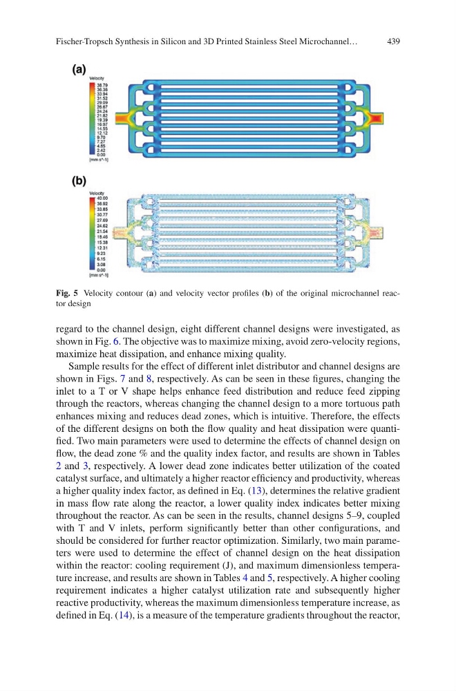
Fig. 5 Velocity contour (a) and velocity vector profiles (b) of the original microchannel reactor design
Fischer-Tropsch Synthesis in Silicon and 3D Printed Stainless Steel Microchannel…
regard to the channel design, eight different channel designs were investigated, as
shown in Fig. 6. The objective was to maximize mixing, avoid zero-velocity regions,
maximize heat dissipation, and enhance mixing quality.
Sample results for the effect of different inlet distributor and channel designs are
shown in Figs. 7 and 8, respectively. As can be seen in these figures, changing the
inlet to a T or V shape helps enhance feed distribution and reduce feed zipping
through the reactors, whereas changing the channel design to a more tortuous path
enhances mixing and reduces dead zones, which is intuitive. Therefore, the effects
of the different designs on both the flow quality and heat dissipation were quantified. Two main parameters were used to determine the effects of channel design on
flow, the dead zone % and the quality index factor, and results are shown in Tables
2 and 3, respectively. A lower dead zone indicates better utilization of the coated
catalyst surface, and ultimately a higher reactor efficiency and productivity, whereas
a higher quality index factor, as defined in Eq. (13), determines the relative gradient
in mass flow rate along the reactor, a lower quality index indicates better mixing
throughout the reactor. As can be seen in the results, channel designs 5–9, coupled
with T and V inlets, perform significantly better than other configurations, and
should be considered for further reactor optimization. Similarly, two main parameters were used to determine the effect of channel design on the heat dissipation
within the reactor: cooling requirement (J), and maximum dimensionless temperature increase, and results are shown in Tables 4 and 5, respectively. A higher cooling
requirement indicates a higher catalyst utilization rate and subsequently higher
reactive productivity, whereas the maximum dimensionless temperature increase, as
defined in Eq. (14), is a measure of the temperature gradients throughout the reactor,
Fig. 5 Velocity contour (a) and velocity vector profiles (b) of the original microchannel reactor design
Fischer-Tropsch Synthesis in Silicon and 3D Printed Stainless Steel Microchannel…