

The transfer function of a measuring system, mentioned above, is indicative of
the phasing between the input signal and sensor output, as well as damping of the
amplitude of the output signal.
For a simplified analysis of complex transfer functions in the frequency domain,
the Laplace transform is typically used (Connor 1978). The Laplace transform is a
generalization of the Fourier transform, (Chap. 3) applicable in situations at instant
t = 0, where the Fourier transform does not lead to a finite solution. The main
difference between the two types of transforms is that while the Fourier transforms
uses positive and negative wave frequencies, the Laplace transforms uses waves
dampened by a e
Àr factor where r is a positive number.
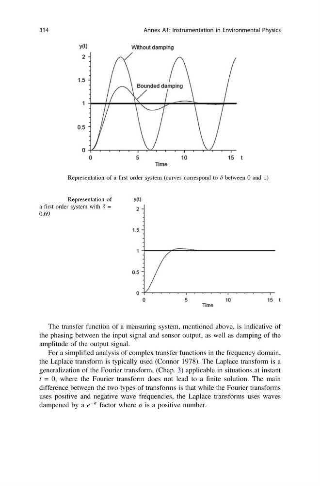
Fig. A1.4 Representation of a first order system (curves correspond to d between 0 and 1)
Fig. A1.5 Representation of
a first order system with d =
0.69
314
Annex A1: Instrumentation in Environmental Physics
the phasing between the input signal and sensor output, as well as damping of the
amplitude of the output signal.
For a simplified analysis of complex transfer functions in the frequency domain,
the Laplace transform is typically used (Connor 1978). The Laplace transform is a
generalization of the Fourier transform, (Chap. 3) applicable in situations at instant
t = 0, where the Fourier transform does not lead to a finite solution. The main
difference between the two types of transforms is that while the Fourier transforms
uses positive and negative wave frequencies, the Laplace transforms uses waves
dampened by a e
Àr factor where r is a positive number.
Fig. A1.4 Representation of a first order system (curves correspond to d between 0 and 1)
Fig. A1.5 Representation of
a first order system with d =
0.69
314
Annex A1: Instrumentation in Environmental Physics