

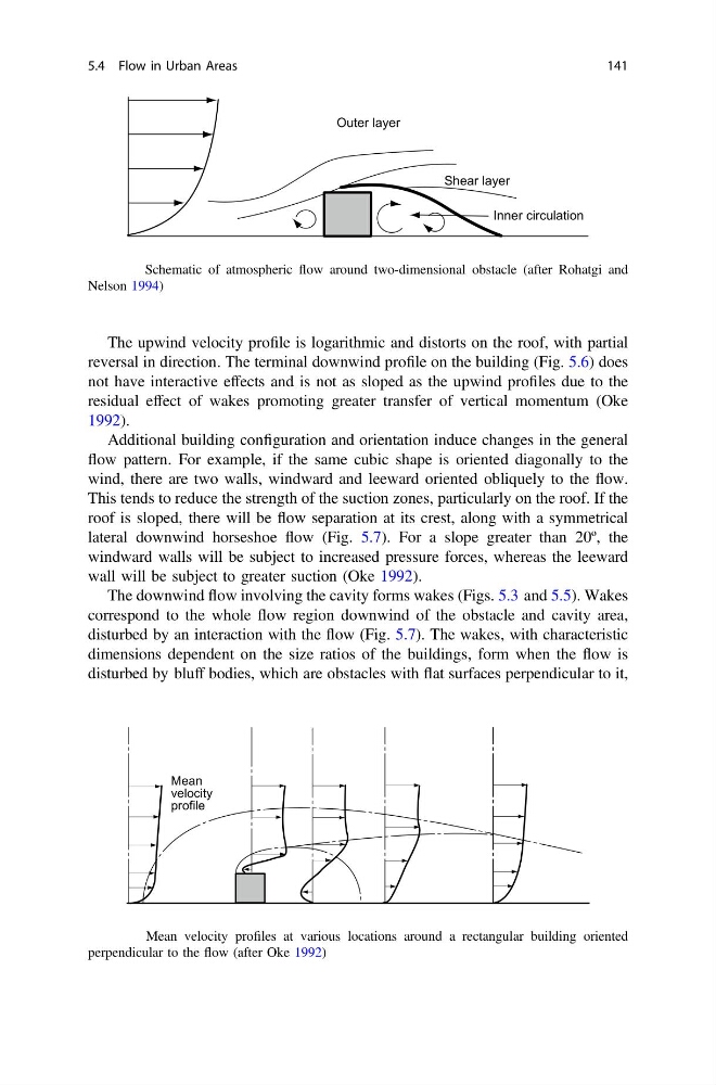
The upwind velocity profile is logarithmic and distorts on the roof, with partial
reversal in direction. The terminal downwind profile on the building (Fig. 5.6) does
not have interactive effects and is not as sloped as the upwind profiles due to the
residual effect of wakes promoting greater transfer of vertical momentum (Oke
1992).
Additional building configuration and orientation induce changes in the general
flow pattern. For example, if the same cubic shape is oriented diagonally to the
wind, there are two walls, windward and leeward oriented obliquely to the flow.
This tends to reduce the strength of the suction zones, particularly on the roof. If the
roof is sloped, there will be flow separation at its crest, along with a symmetrical
lateral downwind horseshoe flow (Fig. 5.7). For a slope greater than 20º, the
windward walls will be subject to increased pressure forces, whereas the leeward
wall will be subject to greater suction (Oke 1992).
The downwind flow involving the cavity forms wakes (Figs. 5.3 and 5.5). Wakes
correspond to the whole flow region downwind of the obstacle and cavity area,
disturbed by an interaction with the flow (Fig. 5.7). The wakes, with characteristic
dimensions dependent on the size ratios of the buildings, form when the flow is
disturbed by bluff bodies, which are obstacles with flat surfaces perpendicular to it,
Outer layer
Shear layer
Inner circulation
Fig. 5.5 Schematic of atmospheric flow around two-dimensional obstacle (after Rohatgi and
Nelson 1994)
Mean
velocity
profile
Fig. 5.6 Mean velocity profiles at various locations around a rectangular building oriented
perpendicular to the flow (after Oke 1992)
5.4 Flow in Urban Areas
141
reversal in direction. The terminal downwind profile on the building (Fig. 5.6) does
not have interactive effects and is not as sloped as the upwind profiles due to the
residual effect of wakes promoting greater transfer of vertical momentum (Oke
1992).
Additional building configuration and orientation induce changes in the general
flow pattern. For example, if the same cubic shape is oriented diagonally to the
wind, there are two walls, windward and leeward oriented obliquely to the flow.
This tends to reduce the strength of the suction zones, particularly on the roof. If the
roof is sloped, there will be flow separation at its crest, along with a symmetrical
lateral downwind horseshoe flow (Fig. 5.7). For a slope greater than 20º, the
windward walls will be subject to increased pressure forces, whereas the leeward
wall will be subject to greater suction (Oke 1992).
The downwind flow involving the cavity forms wakes (Figs. 5.3 and 5.5). Wakes
correspond to the whole flow region downwind of the obstacle and cavity area,
disturbed by an interaction with the flow (Fig. 5.7). The wakes, with characteristic
dimensions dependent on the size ratios of the buildings, form when the flow is
disturbed by bluff bodies, which are obstacles with flat surfaces perpendicular to it,
Outer layer
Shear layer
Inner circulation
Fig. 5.5 Schematic of atmospheric flow around two-dimensional obstacle (after Rohatgi and
Nelson 1994)
Mean
velocity
profile
Fig. 5.6 Mean velocity profiles at various locations around a rectangular building oriented
perpendicular to the flow (after Oke 1992)
5.4 Flow in Urban Areas
141