

12
J. Bujnak et al.
But, the fibre reinforcement in ballast is actually preferred, as new method of reinforcing ballast and maintaining the capability of typical tamping maintenance operations incompatible with geogrids. The addition of propylene fibres from 11 to 47 mm
in length and 0.12 mm in diameter to sand and scaled ballast can minimise the voids
in the mixture as fibre content can increase the compactness.
Continuous box girder as an occasionally preferred option in design of higher
speed bridges, represent another structural type used, especially for crossing of longer
obstacles. Compared to simply supported systems, this bridge type not only exhibits
greater slenderness but also reveals lower dynamic responses. The slenderness ratio,
as span length to cross-section height ranges from 11 to 18. Continuous box girders
can be designed as having either uniform or variable depth.
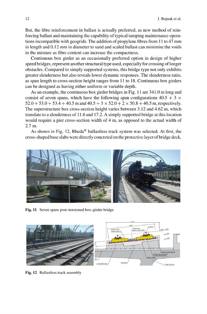
As an example, the continuous box girder bridges in Fig. 11 are 341.0 m long and
consist of seven spans, which have the following span configurations 40.5 + 3 ×
52.0 + 53.0 + 53.4 + 40.5 m and 40.5 + 3 × 52.0 + 2 × 50.8 + 40.5 m, respectively.
The superstructure box cross-section height varies between 3.12 and 4.62 m, which
translate to a slenderness of 11.6 and 17.2. A simply supported bridge at this location
would require a pier cross-section width of 4 m, as opposed to the actual width of
2.7 m.
As shown in Fig. 12, Rheda
® ballastless track system was selected. At first, the
cross-shaped base slabs were directly concreted on the protective layer of bridge deck.
Fig. 11 Seven spans post–tensioned box–girder bridge
Fig. 12 Ballastless track assembly
J. Bujnak et al.
But, the fibre reinforcement in ballast is actually preferred, as new method of reinforcing ballast and maintaining the capability of typical tamping maintenance operations incompatible with geogrids. The addition of propylene fibres from 11 to 47 mm
in length and 0.12 mm in diameter to sand and scaled ballast can minimise the voids
in the mixture as fibre content can increase the compactness.
Continuous box girder as an occasionally preferred option in design of higher
speed bridges, represent another structural type used, especially for crossing of longer
obstacles. Compared to simply supported systems, this bridge type not only exhibits
greater slenderness but also reveals lower dynamic responses. The slenderness ratio,
as span length to cross-section height ranges from 11 to 18. Continuous box girders
can be designed as having either uniform or variable depth.
As an example, the continuous box girder bridges in Fig. 11 are 341.0 m long and
consist of seven spans, which have the following span configurations 40.5 + 3 ×
52.0 + 53.0 + 53.4 + 40.5 m and 40.5 + 3 × 52.0 + 2 × 50.8 + 40.5 m, respectively.
The superstructure box cross-section height varies between 3.12 and 4.62 m, which
translate to a slenderness of 11.6 and 17.2. A simply supported bridge at this location
would require a pier cross-section width of 4 m, as opposed to the actual width of
2.7 m.
As shown in Fig. 12, Rheda
® ballastless track system was selected. At first, the
cross-shaped base slabs were directly concreted on the protective layer of bridge deck.
Fig. 11 Seven spans post–tensioned box–girder bridge
Fig. 12 Ballastless track assembly