

Innovative Bridge Concept
11
obtained from measurement. In the static loading test, a heavy emergency railway
crane EDK 750 was used as live-load in specified configurations.
Arch bridges are generally considered to be better looking than truss systems as far
as aesthetics in challenging, mainly city environment. As next advantage, the single
span tied arch reacts on the supporting substructure as if it were a simply supported
beam. Internally, however, the system is indeterminate with the behaviour being
dependent on the ratio of the tie stiffness to the other structural element stiffness.
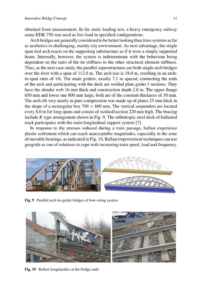
Thus, as the next case study, the parallel superstructures are both single-arch bridges
over the river with a span of 112.0 m. The arch rise is 18.0 m, resulting in an archto-span ratio of 1/6. The main girders, axially 7.1 m spaced, connecting the ends
of the arch and participating with the deck are welded plate girder I sections. They
have the slender web 16 mm thick and construction depth 2.8 m. The upper flange
650 mm and lower one 800 mm large, both are of the constant thickness of 30 mm.
The arch rib very nearly in pure compression was made up of plates 25 mm thick in
the shape of a rectangular box 700 × 600 mm. The vertical suspenders are located
every 8.0 m for long spans and consist of weldedIsection 220 mm high. The bracing
include K type arrangement shown in Fig. 9. The orthotropic steel deck of ballasted
track participates with the main longitudinal support system [7].
In response to the stresses induced during a train passage, ballast experience
plastic settlement which can reach unacceptable magnitudes, especially in the zone
of movable bearings, as indicated in Fig. 10. Ballast improvement techniques can use
geogrids as one of solutions to cope with increasing train speed, load and frequency.
Fig. 9 Parallel arch tie-girder bridges of bow-string system
Fig. 10 Ballast irregularities at the bridge ends
11
obtained from measurement. In the static loading test, a heavy emergency railway
crane EDK 750 was used as live-load in specified configurations.
Arch bridges are generally considered to be better looking than truss systems as far
as aesthetics in challenging, mainly city environment. As next advantage, the single
span tied arch reacts on the supporting substructure as if it were a simply supported
beam. Internally, however, the system is indeterminate with the behaviour being
dependent on the ratio of the tie stiffness to the other structural element stiffness.
Thus, as the next case study, the parallel superstructures are both single-arch bridges
over the river with a span of 112.0 m. The arch rise is 18.0 m, resulting in an archto-span ratio of 1/6. The main girders, axially 7.1 m spaced, connecting the ends
of the arch and participating with the deck are welded plate girder I sections. They
have the slender web 16 mm thick and construction depth 2.8 m. The upper flange
650 mm and lower one 800 mm large, both are of the constant thickness of 30 mm.
The arch rib very nearly in pure compression was made up of plates 25 mm thick in
the shape of a rectangular box 700 × 600 mm. The vertical suspenders are located
every 8.0 m for long spans and consist of weldedIsection 220 mm high. The bracing
include K type arrangement shown in Fig. 9. The orthotropic steel deck of ballasted
track participates with the main longitudinal support system [7].
In response to the stresses induced during a train passage, ballast experience
plastic settlement which can reach unacceptable magnitudes, especially in the zone
of movable bearings, as indicated in Fig. 10. Ballast improvement techniques can use
geogrids as one of solutions to cope with increasing train speed, load and frequency.
Fig. 9 Parallel arch tie-girder bridges of bow-string system
Fig. 10 Ballast irregularities at the bridge ends