

132
S. Grzeszczyk and K. Jurowski
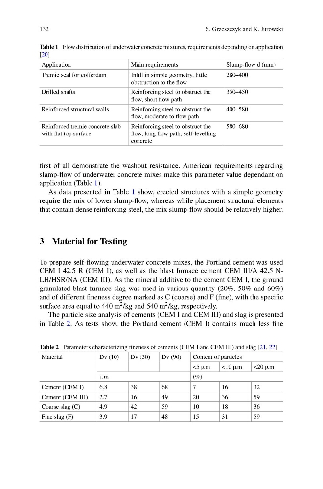
Table 1 Flow distribution of underwater concrete mixtures, requirements depending on application
[20]
Application
Main requirements
Slump-flow d (mm)
Tremie seal for cofferdam
Infill in simple geometry, little
obstruction to the flow
280–400
Drilled shafts
Reinforcing steel to obstruct the
flow, short flow path
350–450
Reinforced structural walls
Reinforcing steel to obstruct the
flow, moderate to flow path
400–580
Reinforced tremie concrete slab
with flat top surface
Reinforcing steel to obstruct the
flow, long flow path, self-levelling
concrete
580–680
first of all demonstrate the washout resistance. American requirements regarding
slamp-flow of underwater concrete mixes make this parameter value dependant on
application (Table 1).
As data presented in Table 1 show, erected structures with a simple geometry
require the mix of lower slump-flow, whereas while placement structural elements
that contain dense reinforcing steel, the mix slump-flow should be relatively higher.
3 Material for Testing
To prepare self-flowing underwater concrete mixes, the Portland cement was used
CEM I 42.5 R (CEM I), as well as the blast furnace cement CEM III/A 42.5 NLH/HSR/NA (CEM III). As the mineral additive to the cement CEM I, the ground
granulated blast furnace slag was used in various quantity (20%, 50% and 60%)
and of different fineness degree marked as C (coarse) and F (fine), with the specific
surface area equal to 440 m
2 /kg and 540 m
2 /kg, respectively.
The particle size analysis of cements (CEM I and CEM III) and slag is presented
in Table 2. As tests show, the Portland cement (CEM I) contains much less fine
Table 2 Parameters characterizing fineness of cements (CEM I and CEM III) and slag [21, 22]
Material
Dv (10)
Dv (50)
Dv (90)
Content of particles
<5 µm
<10 µm
<20 µm
µm
(%)
Cement (CEM I)
6.8
38
68
7
16
32
Cement (CEM III)
2.7
16
49
20
36
59
Coarse slag (C)
4.9
42
59
10
18
36
Fine slag (F)
3.9
17
48
15
31
59
S. Grzeszczyk and K. Jurowski
Table 1 Flow distribution of underwater concrete mixtures, requirements depending on application
[20]
Application
Main requirements
Slump-flow d (mm)
Tremie seal for cofferdam
Infill in simple geometry, little
obstruction to the flow
280–400
Drilled shafts
Reinforcing steel to obstruct the
flow, short flow path
350–450
Reinforced structural walls
Reinforcing steel to obstruct the
flow, moderate to flow path
400–580
Reinforced tremie concrete slab
with flat top surface
Reinforcing steel to obstruct the
flow, long flow path, self-levelling
concrete
580–680
first of all demonstrate the washout resistance. American requirements regarding
slamp-flow of underwater concrete mixes make this parameter value dependant on
application (Table 1).
As data presented in Table 1 show, erected structures with a simple geometry
require the mix of lower slump-flow, whereas while placement structural elements
that contain dense reinforcing steel, the mix slump-flow should be relatively higher.
3 Material for Testing
To prepare self-flowing underwater concrete mixes, the Portland cement was used
CEM I 42.5 R (CEM I), as well as the blast furnace cement CEM III/A 42.5 NLH/HSR/NA (CEM III). As the mineral additive to the cement CEM I, the ground
granulated blast furnace slag was used in various quantity (20%, 50% and 60%)
and of different fineness degree marked as C (coarse) and F (fine), with the specific
surface area equal to 440 m
2 /kg and 540 m
2 /kg, respectively.
The particle size analysis of cements (CEM I and CEM III) and slag is presented
in Table 2. As tests show, the Portland cement (CEM I) contains much less fine
Table 2 Parameters characterizing fineness of cements (CEM I and CEM III) and slag [21, 22]
Material
Dv (10)
Dv (50)
Dv (90)
Content of particles
<5 µm
<10 µm
<20 µm
µm
(%)
Cement (CEM I)
6.8
38
68
7
16
32
Cement (CEM III)
2.7
16
49
20
36
59
Coarse slag (C)
4.9
42
59
10
18
36
Fine slag (F)
3.9
17
48
15
31
59