

Fourier and Laplace
355
R.4.100 The voltage across a capacitor C, denoted by v C (t) is expressed in the time domain
and its equivalent in the frequency domain as follows by (using FT properties):
v t
C
i
d
V s
I s
sC
V
s
C
c
c
t
C
( )
( )
( )
( )
( )
ϭ
ϭ
ϩ
1
0
↔
∞
∫
Ϫ
Recall that V C (0) denotes the initial voltage v C (t) at t = 0.
R.4.101 For example, let us analyze the case of a capacitor C of 2 F, charged with an initial
voltage of +5 V. Then its frequency domain representation, using the LT is given by
V s
I s
s
s
C ( )
( )
ϭ
ϩ
2
5
R.4.102 Note that if V C (s) =
I(s)
___
sC
, then the impedance of the capacitor C in the frequency
domain is given by
X s
sC
C ( )ϭ
1
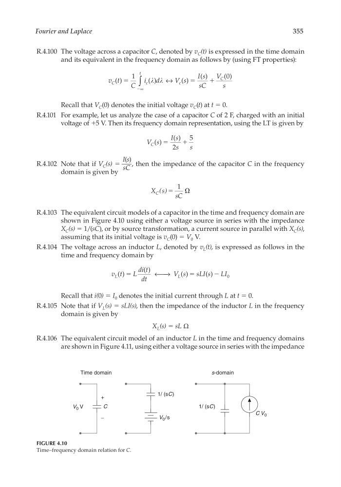
R.4.103 The equivalent circuit models of a capacitor in the time and frequency domain are
shown in Figure 4.10 using either a voltage source in series with the impedance
X C (s) = 1/(sC), or by source transformation, a current source in parallel with X C (s),
assuming that its initial voltage is v C (0) = V 0 V.
R.4.104 The voltage across an inductor L, denoted by v L (t), is expressed as follows in the
time and frequency domain by
v t
L
di t
dt
V s
sLI s
LI
L
L
( )
( )
( )
( )
ϭ
ϭ
← →
Ϫ 0
Recall that i(0) = I 0 denotes the initial current through L at t = 0.
R.4.105 Note that if V L (s) = sLI(s), then the impedance of the inductor L in the frequency
domain is given by
X L (s) = sL Ω
R.4.106 The equivalent circuit model of an inductor L in the time and frequency domains
are shown in Figure 4.11, using either a voltage source in series with the impedance
Time domain
s-domain
C
+
−
V 0 V
1/ (sC)
1/ (sC)
V 0 /s
C V 0
FIGURE 4.10
Time–frequency domain relation for C.
CRC_47760_CH004.indd 355
CRC_47760_CH004.indd 355
7/28/2008 12:25:59 PM
7/28/2008 12:25:59 PM
355
R.4.100 The voltage across a capacitor C, denoted by v C (t) is expressed in the time domain
and its equivalent in the frequency domain as follows by (using FT properties):
v t
C
i
d
V s
I s
sC
V
s
C
c
c
t
C
( )
( )
( )
( )
( )
ϭ
ϭ
ϩ
1
0
↔
∞
∫
Ϫ
Recall that V C (0) denotes the initial voltage v C (t) at t = 0.
R.4.101 For example, let us analyze the case of a capacitor C of 2 F, charged with an initial
voltage of +5 V. Then its frequency domain representation, using the LT is given by
V s
I s
s
s
C ( )
( )
ϭ
ϩ
2
5
R.4.102 Note that if V C (s) =
I(s)
___
sC
, then the impedance of the capacitor C in the frequency
domain is given by
X s
sC
C ( )ϭ
1
R.4.103 The equivalent circuit models of a capacitor in the time and frequency domain are
shown in Figure 4.10 using either a voltage source in series with the impedance
X C (s) = 1/(sC), or by source transformation, a current source in parallel with X C (s),
assuming that its initial voltage is v C (0) = V 0 V.
R.4.104 The voltage across an inductor L, denoted by v L (t), is expressed as follows in the
time and frequency domain by
v t
L
di t
dt
V s
sLI s
LI
L
L
( )
( )
( )
( )
ϭ
ϭ
← →
Ϫ 0
Recall that i(0) = I 0 denotes the initial current through L at t = 0.
R.4.105 Note that if V L (s) = sLI(s), then the impedance of the inductor L in the frequency
domain is given by
X L (s) = sL Ω
R.4.106 The equivalent circuit model of an inductor L in the time and frequency domains
are shown in Figure 4.11, using either a voltage source in series with the impedance
Time domain
s-domain
C
+
−
V 0 V
1/ (sC)
1/ (sC)
V 0 /s
C V 0
FIGURE 4.10
Time–frequency domain relation for C.
CRC_47760_CH004.indd 355
CRC_47760_CH004.indd 355
7/28/2008 12:25:59 PM
7/28/2008 12:25:59 PM