

Alternating Current Analysis
259
Then the currents of the circuit diagram shown in Figure 3.34 are evaluated by the
algebraic addition of the individual contributions of each source (superposition
principle), yielding the following:
i 1 (t) = I A1 + i B1 (t)
i 1 (t) = 5 − √
__
2 cos(10t − 45°) A
i 2 (t) = I A2 + i B2 (t)
i 2 (t) = √
__
2 cos(10t − 45°) A
i 3 (t) = I A3 − i B3 (t)
i 3 (t) = 5 − 2 √
__
2 cos(10t − 45°) A
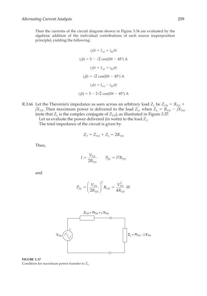
R.3.66 Let the Thevenin’s impedance as seen across an arbitrary load Z L be Z TH = R TH +
jX TH . Then maximum power is delivered to the load Z L , when Z L = R TH − jX TH
(note that Z L is the complex conjugate of Z TH ), as illustrated in Figure 3.37.
Let us evaluate the power delivered (in watts) to the load Z L .
The total impedance of the circuit is given by
Z T = Z TH + Z L = 2R TH
Then,
I
V
R
P
I R
TH
TH
RL
TH
ϭ
ϭ
2
2
and
P
V
R
R
V
R
W
ZL
TH
TH
TH
TH
TH
ϭ
ϭ
2
4
2
2
+
−
V TH
Z TH = R TH + j X TH
Z L = R TH − j X TH
FIGURE 3.37
Condition for maximum power transfer to Z L .
CRC_47760_CH003.indd 259
CRC_47760_CH003.indd 259
7/23/2008 1:27:40 PM
7/23/2008 1:27:40 PM
259
Then the currents of the circuit diagram shown in Figure 3.34 are evaluated by the
algebraic addition of the individual contributions of each source (superposition
principle), yielding the following:
i 1 (t) = I A1 + i B1 (t)
i 1 (t) = 5 − √
__
2 cos(10t − 45°) A
i 2 (t) = I A2 + i B2 (t)
i 2 (t) = √
__
2 cos(10t − 45°) A
i 3 (t) = I A3 − i B3 (t)
i 3 (t) = 5 − 2 √
__
2 cos(10t − 45°) A
R.3.66 Let the Thevenin’s impedance as seen across an arbitrary load Z L be Z TH = R TH +
jX TH . Then maximum power is delivered to the load Z L , when Z L = R TH − jX TH
(note that Z L is the complex conjugate of Z TH ), as illustrated in Figure 3.37.
Let us evaluate the power delivered (in watts) to the load Z L .
The total impedance of the circuit is given by
Z T = Z TH + Z L = 2R TH
Then,
I
V
R
P
I R
TH
TH
RL
TH
ϭ
ϭ
2
2
and
P
V
R
R
V
R
W
ZL
TH
TH
TH
TH
TH
ϭ
ϭ
2
4
2
2
+
−
V TH
Z TH = R TH + j X TH
Z L = R TH − j X TH
FIGURE 3.37
Condition for maximum power transfer to Z L .
CRC_47760_CH003.indd 259
CRC_47760_CH003.indd 259
7/23/2008 1:27:40 PM
7/23/2008 1:27:40 PM