

260
Practical MATLAB
® Applications for Engineers
R.3.67 Let the load impedance of an arbitrary network be Z L = R L + jX L , where R L can be
adjusted (variable), and let the load reactance X L be fi xed, where X L ≠ X TH . Then
maximum power delivered to the load Z L occurs when R L is (adjusted) to
R
R
X
X
L
TH
TH
L
ϭ
ϩ
ϩ
2
2
(
)
and the power delivered to the load is then
P
V R
RL
TH X
ϭ
2
4
where
R
R
R
X
TH
L
ϭ
ϩ
2
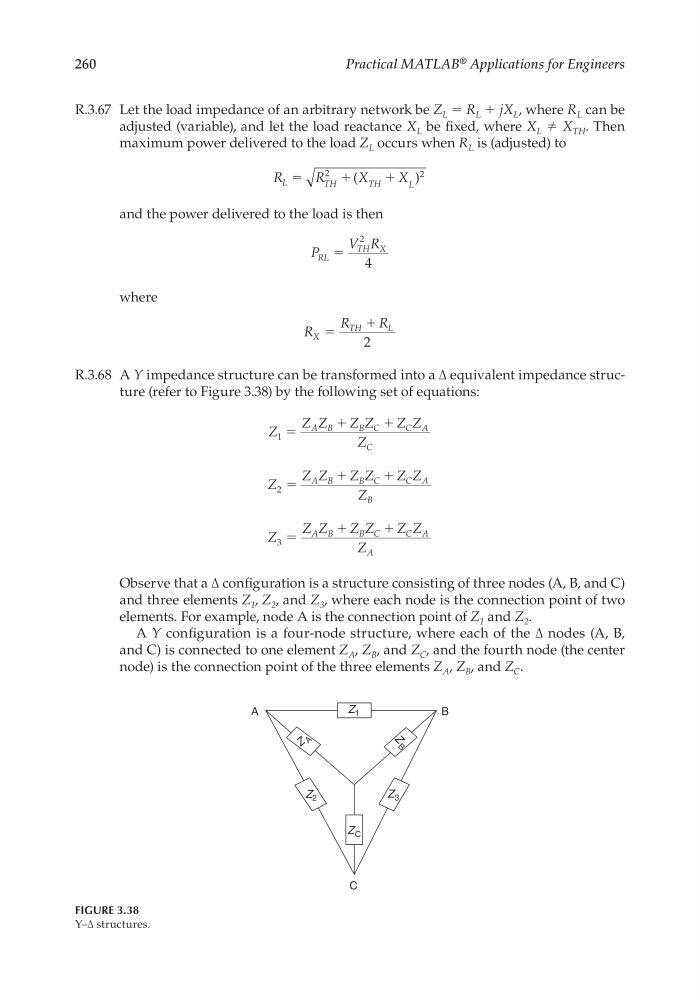
R.3.68 A Y impedance structure can be transformed into a ∆ equivalent impedance structure (refer to Figure 3.38) by the following set of equations:
Z
Z Z
Z Z
Z Z
Z
A B
B C
C A
C
1 ϭ
ϩ
ϩ
Z
Z Z
Z Z
Z Z
Z
A B
B C
C A
B
2 ϭ
ϩ
ϩ
Z
Z Z
Z Z
Z Z
Z
A B
B C
C A
A
3 ϭ
ϩ
ϩ
Observe that a ∆ confi guration is a structure consisting of three nodes (A, B, and C)
and three elements Z 1 , Z 2 , and Z 3 , where each node is the connection point of two
elements. For example, node A is the connection point of Z 1 and Z 2 .
A Y confi guration is a four-node structure, where each of the ∆ nodes (A, B,
and C) is connected to one element Z A , Z B , and Z C , and the fourth node (the center
node) is the connection point of the three elements Z A , Z B , and Z C .
Z 2
Z 3
Z 1
Z A
Z C
Z
B
B
A
C
FIGURE 3.38
Y–∆ structures.
CRC_47760_CH003.indd 260
CRC_47760_CH003.indd 260
7/23/2008 1:27:41 PM
7/23/2008 1:27:41 PM
Practical MATLAB
® Applications for Engineers
R.3.67 Let the load impedance of an arbitrary network be Z L = R L + jX L , where R L can be
adjusted (variable), and let the load reactance X L be fi xed, where X L ≠ X TH . Then
maximum power delivered to the load Z L occurs when R L is (adjusted) to
R
R
X
X
L
TH
TH
L
ϭ
ϩ
ϩ
2
2
(
)
and the power delivered to the load is then
P
V R
RL
TH X
ϭ
2
4
where
R
R
R
X
TH
L
ϭ
ϩ
2
R.3.68 A Y impedance structure can be transformed into a ∆ equivalent impedance structure (refer to Figure 3.38) by the following set of equations:
Z
Z Z
Z Z
Z Z
Z
A B
B C
C A
C
1 ϭ
ϩ
ϩ
Z
Z Z
Z Z
Z Z
Z
A B
B C
C A
B
2 ϭ
ϩ
ϩ
Z
Z Z
Z Z
Z Z
Z
A B
B C
C A
A
3 ϭ
ϩ
ϩ
Observe that a ∆ confi guration is a structure consisting of three nodes (A, B, and C)
and three elements Z 1 , Z 2 , and Z 3 , where each node is the connection point of two
elements. For example, node A is the connection point of Z 1 and Z 2 .
A Y confi guration is a four-node structure, where each of the ∆ nodes (A, B,
and C) is connected to one element Z A , Z B , and Z C , and the fourth node (the center
node) is the connection point of the three elements Z A , Z B , and Z C .
Z 2
Z 3
Z 1
Z A
Z C
Z
B
B
A
C
FIGURE 3.38
Y–∆ structures.
CRC_47760_CH003.indd 260
CRC_47760_CH003.indd 260
7/23/2008 1:27:41 PM
7/23/2008 1:27:41 PM