

Alternating Current Analysis
257
R.3.64 The superposition principle for the AC case follows closely to the DC case discussed
in Chapter 2, that is, in a linear network containing n sources (not necessarily with
the same frequencies) any network current or voltage is the algebraic sum of the
responses or contributions due to each of the n sources acting separately by forcing
all the remaining n – 1 sources to zero.
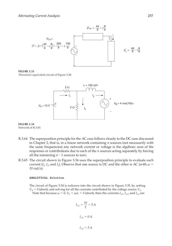
R.3.65 The circuit shown in Figure 3.34 uses the superposition principle to evaluate each
current (I 1 , I 2 , and I 3 ). Observe that one source is DC and the other is AC (with ω =
10 rad/s).
ANALYTICAL Solution
The circuit of Figure 3.34 is redrawn into the circuit shown in Figure 3.35, by setting
V B = 0 (short), and solving for all the currents contributed by the voltage source V A .
Note that because ω = 0, X L = jωL = 0 (short), then the currents I A1 , I A2 , and I A3 are
I A1
10
2
5
ϭ
ϭ A
I A2 0
ϭ A
I A3 5
ϭ A
V TH =
(
)
9
100
9
300
9
8
9
44
*
)
7
(
j
j
j
+
+
−
=
+
+
Z L =
9
8
9
46 j
−
Z TH =
9
8
9
44 j
+
I L
FIGURE 3.33
Thevenin’s equivalent circuit of Figure 3.28.
V B = 4 cos(10t)υ
V A = 10 V
I 3
I 2
L = 100 mH
2 Ω
2 Ω
I 1
+
−
+
−
FIGURE 3.34
Network of R.3.65.
CRC_47760_CH003.indd 257
CRC_47760_CH003.indd 257
7/23/2008 1:27:39 PM
7/23/2008 1:27:39 PM
257
R.3.64 The superposition principle for the AC case follows closely to the DC case discussed
in Chapter 2, that is, in a linear network containing n sources (not necessarily with
the same frequencies) any network current or voltage is the algebraic sum of the
responses or contributions due to each of the n sources acting separately by forcing
all the remaining n – 1 sources to zero.
R.3.65 The circuit shown in Figure 3.34 uses the superposition principle to evaluate each
current (I 1 , I 2 , and I 3 ). Observe that one source is DC and the other is AC (with ω =
10 rad/s).
ANALYTICAL Solution
The circuit of Figure 3.34 is redrawn into the circuit shown in Figure 3.35, by setting
V B = 0 (short), and solving for all the currents contributed by the voltage source V A .
Note that because ω = 0, X L = jωL = 0 (short), then the currents I A1 , I A2 , and I A3 are
I A1
10
2
5
ϭ
ϭ A
I A2 0
ϭ A
I A3 5
ϭ A
V TH =
(
)
9
100
9
300
9
8
9
44
*
)
7
(
j
j
j
+
+
−
=
+
+
Z L =
9
8
9
46 j
−
Z TH =
9
8
9
44 j
+
I L
FIGURE 3.33
Thevenin’s equivalent circuit of Figure 3.28.
V B = 4 cos(10t)υ
V A = 10 V
I 3
I 2
L = 100 mH
2 Ω
2 Ω
I 1
+
−
+
−
FIGURE 3.34
Network of R.3.65.
CRC_47760_CH003.indd 257
CRC_47760_CH003.indd 257
7/23/2008 1:27:39 PM
7/23/2008 1:27:39 PM