

Alternating Current Analysis
233
Observe that the phase angle θ between the current i R (t) and the voltage v R (t) in a
resistive circuit is zero, a condition that is referred to as in phase.
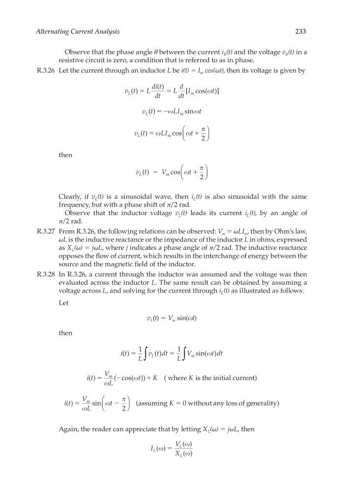
R.3.26 Let the current through an inductor L be i(t) = I m cos(ωt), then its voltage is given by
v t
L
di t
dt
L
d
dt
I
t
L
m
( )
( )
[ cos( )]
ϭ
ϭ
v t
LI
t
L
m
( )
sin
ϭ Ϫ
v t
LI
t
L
m
( )
cos
ϭ
ϩ
2
then
v t
V
t
L
m
( ) ϭ
ϩ
cos
2
Clearly, if v L (t) is a sinusoidal wave, then i L (t) is also sinusoidal with the same
frequency, but with a phase shift of π/2 rad.
Observe that the inductor voltage v L (t) leads its current i L (t), by an angle of
π/2 rad.
R.3.27 From R.3.26, the following relations can be observed: V m = ωLI m , then by Ohm’s law,
ωL is the inductive reactance or the impedance of the inductor L in ohms, expressed
as X L (ω) = jωL, where j indicates a phase angle of π/2 rad. The inductive reactance
opposes the fl ow of current, which results in the interchange of energy between the
source and the magnetic fi eld of the inductor.
R.3.28 In R.3.26, a current through the inductor was assumed and the voltage was then
evaluated across the inductor L. The same result can be obtained by assuming a
voltage across L, and solving for the current through i L (t) as illustrated as follows:
Let
v L (t) = V m sin(t)
then
i t
L
v t dt
L
V
t dt
L
m
( )
( )
sin( )
ϭ
ϭ
1
1
∫
∫
i t
V
L
t
K
m
( )
( cos( ))
ϭ
Ϫ
ϩ
( where is the initial current)
K
i t
V
L
t
K
m
( )
sin
ϭ
Ϫ
ϭ
2
(as uming
0 w h
s
i to u t a n y l o s s o f g e enerality)
Again, the reader can appreciate that by letting X L (ω) = jωL, then
I
V
X
L
L
L
( )
( )
( )
ϭ
CRC_47760_CH003.indd 233
CRC_47760_CH003.indd 233
7/23/2008 1:27:31 PM
7/23/2008 1:27:31 PM
233
Observe that the phase angle θ between the current i R (t) and the voltage v R (t) in a
resistive circuit is zero, a condition that is referred to as in phase.
R.3.26 Let the current through an inductor L be i(t) = I m cos(ωt), then its voltage is given by
v t
L
di t
dt
L
d
dt
I
t
L
m
( )
( )
[ cos( )]
ϭ
ϭ
v t
LI
t
L
m
( )
sin
ϭ Ϫ
v t
LI
t
L
m
( )
cos
ϭ
ϩ
2
then
v t
V
t
L
m
( ) ϭ
ϩ
cos
2
Clearly, if v L (t) is a sinusoidal wave, then i L (t) is also sinusoidal with the same
frequency, but with a phase shift of π/2 rad.
Observe that the inductor voltage v L (t) leads its current i L (t), by an angle of
π/2 rad.
R.3.27 From R.3.26, the following relations can be observed: V m = ωLI m , then by Ohm’s law,
ωL is the inductive reactance or the impedance of the inductor L in ohms, expressed
as X L (ω) = jωL, where j indicates a phase angle of π/2 rad. The inductive reactance
opposes the fl ow of current, which results in the interchange of energy between the
source and the magnetic fi eld of the inductor.
R.3.28 In R.3.26, a current through the inductor was assumed and the voltage was then
evaluated across the inductor L. The same result can be obtained by assuming a
voltage across L, and solving for the current through i L (t) as illustrated as follows:
Let
v L (t) = V m sin(t)
then
i t
L
v t dt
L
V
t dt
L
m
( )
( )
sin( )
ϭ
ϭ
1
1
∫
∫
i t
V
L
t
K
m
( )
( cos( ))
ϭ
Ϫ
ϩ
( where is the initial current)
K
i t
V
L
t
K
m
( )
sin
ϭ
Ϫ
ϭ
2
(as uming
0 w h
s
i to u t a n y l o s s o f g e enerality)
Again, the reader can appreciate that by letting X L (ω) = jωL, then
I
V
X
L
L
L
( )
( )
( )
ϭ
CRC_47760_CH003.indd 233
CRC_47760_CH003.indd 233
7/23/2008 1:27:31 PM
7/23/2008 1:27:31 PM